The Buildings
home | the buildings | admiralty test house (307) | technical specification

|
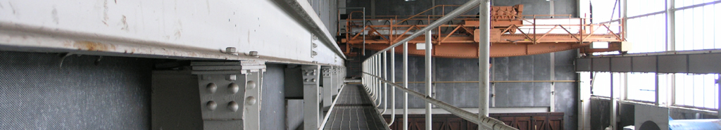
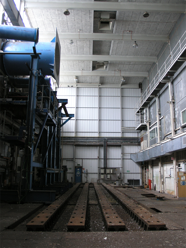
The turbine hall looking south.
23|05|07 © Simon Cornwell 2007
|
Applications
The Admiralty Test House was designed specifically for the testing of marine gas turbine engines in representative
shipboard enclosures over their full power range up to 30 MW. It can cater for long term development and endurance testing and is
also capable of testing industrial engines.
Dimensions
The facility consists of a flat test bed 3m wide and 22m long. The engine enclosure is situated on the front half and the torque
measuring systems, gear box and dynamometers are on the latter 9m.
Capabilities
Hydraulic dynamometers absorb the power generated by the engine up to 30MW. These can be pre-programmed with a variety of torque curves
to suit the engine test power absorption requirements.
Up to 80 Kg/s of air can be drawn through a plenum chamber, containing filters and acoustic splitters, where it is drawn into an air meter
to allow accurate massflow measurement. An additional engine enclosure ventilating system is situated adjacent to the inlet plenum chamber.
This incorporates a variable speed fan that can deliver a maxiumum air massflow of 13.6 Kg/s. The exhaust gasses are vented to atmosphere
via an exhaust detuner.
Four Houchin Air Smart Trolleys rated at 1.35 Kg/s each, provide air at 350 KPaG. High pressure air is stored in cylinders primarily
to drive emergency backup systems in the event of electrical power failure, however, this stored high pressure air can be used to undertake
engine starts.
Special Features
A versatile water system provides cooling requirements for the engine and its associated auxiliary plant. A demineralised water
supply is available for specialist applications such as compressor washing or mixing to make cooling solutions.
Two fuel pumps feed the engine enclosure from the facility's holding tanks, and each can deliver 1.5 l/s flow. This flow/return
sutem incorporates an emergency rundown tank.
A salt spray injection into the air intake is available to simulate the marine environment. In addition, a highly versatile compressor
washing system is also available.
Summary Of Data
| Ambient |
80 Kg/s |
3 m |
22 m |
Sea Level |
30 MW |
3 l/s |
40 MW |
Marine/Industrial
Engine Testing |

© DERA 1995-2001
Taken from a DERA Brochure
|