The Buildings
home | the buildings | cells 1 & 2 (561)
Cells 1 & 2 (561)
Built: 1957
Decommissioned: 2002
As the "new site" took shape and the futuristic steel-framed brick buildings of the Power Station,
Admiralty Test House and
Battle Test House were completed, building started on one of the oddest looking constructions
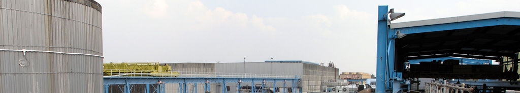
on the site. A huge steel shed sheltered a number of buildings and two, parallel steel tubes, whilst an enormous concrete wedge-shaped
structure rose up at its rear, dominating the early site.
It was almost the complete opposite to the huge, squat blockhouse of the
Plant House next to it, another example of the architectural quip that "form follows function."
The Plant House was dedicated to the specialised testing of discrete components and its structure encompassed
an array of testing rooms; whilst Cells 1 and 2 was designed to fire up and run a whole gas turbine and so it only required two
large test cells, control room and exhaust silencer. It was also the reason why the �new site� was originally constructed.
|
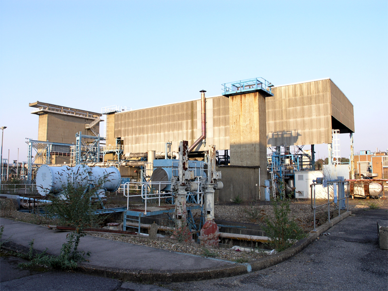
Sunset on the western flank of Cells 1 & 2. The
Silenced Exhaust can be seen to the left.
03|03|07 © Simon Cornwell 2007
|
Cells 1 and 2 was the first altitude test cell to be completed at Pyestock in 1957. Tasked with the competing requirements
of both free jet testing (where the engine intake performance could be tested under supersonic conditions) and connected jet testing (where the engine
was connected directly to the air supply and tested for integrity and combustion), the early designers elected to build two similar, parallel test cells.
Cell 1 would be used for free jet testing whilst connected jet testing would be undertaken in Cell 2.
Costs were saved by sharing facilities such as fuel and water supplies, exhaust silencing and control room.
A large steel framed shelter was built under which were located part of the tubular test cells, the brick blast-proof control room which separated them, and
the fuel and water supplies. Both cells were 3.7 metres in diameter and 35 metres in length of which a 2 metre diameter section of 8 metre length was available
for engine installation. Glass viewing windows led into the control room where the engine under test could be observed.
The massive concrete exhaust stack was unique to Pyestock and allowed the exhaust gases to be vented safely and relatively silently.

|
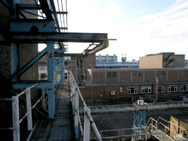
Cell 1 and 2 control room looking south.
21|04|07 © Simon Cornwell 2007
|
Air supplies originally came from the neighbouring Plant House but limited connections were added when the
Air House was built several years later. The air could be preheated in a 3MV heater to a maximum of 350°C. The minimum temperature was 70°C,
but extra plumbing to the Cell 3 Air Cooler, allowed this to be dropped to 30°C (and during a particularly cold winter snap could be expected to
drop to 10°C).
The fuel system could pump fuel to the engine under test at 16000 gal/hour at a pressure of 1500 lb/in.
|
|
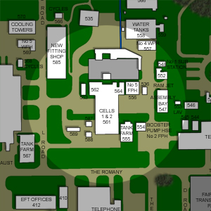
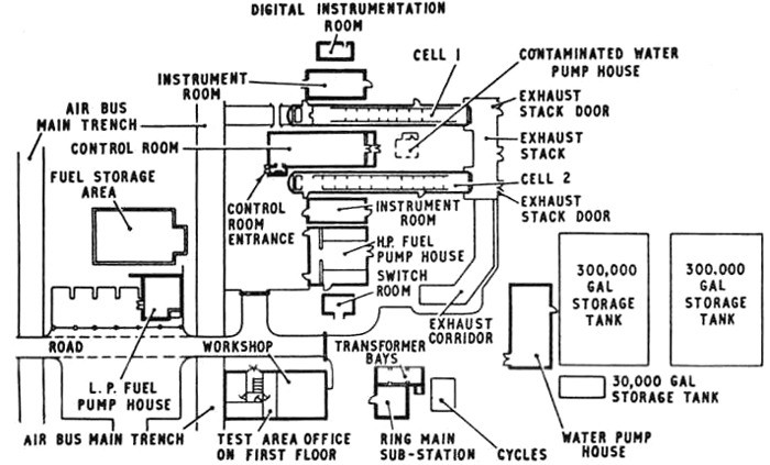
Layout of E.T.F. Cells 1 and 2
|
The cell had its own a re-circulating water supply for cooling the exhaust gases via direct water injection through spray nozzles. Two systems were available giving
a maximum injection rate of 180000 gal/hour from the water storage tanks which had a capacity of 600,000 gallons.
All engine test information was fed through to the on-line SDS 9300 computer (with its peripheral PDP7 for data acquisition) in the
Computer Building where results could be collected and analysed. The same system was retained when the computers were upgraded
to the ICL 1904S main computer and its PDP 11/10 data slave. Experimental information could also be obtained by photographic means.
|
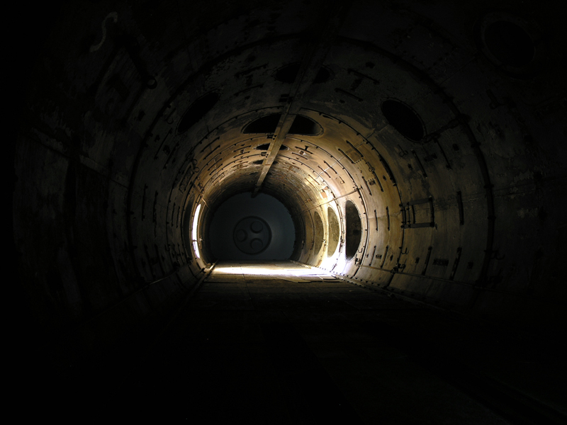
Interior of Cell 1 looking north-east.
21|04|07 © Simon Cornwell 2007
|
The area was originally known as the Ramjet Testing Area as ramjets were initially tested in Cell 1 � but both cells were fully capable
of testing gas turbines. The naming of the test cells soon reverted to Cells 1 and 2 when they became eclipsed by their successors, the massive
Cell 3 and equally huge Cell 4. Cells 1 and 2 did not fall into disuse though and were
used for full-scale testing of turbojet and ramjet engines and for component development work under sea level and simulated altitude conditions. It doesn't look
like the cells were mothballed either (unlike Cell 4) and the upgrading of its control room suggests that it remained in use until
the majority of the site closed in the early 2000s.
Cells 1 & 2 Walkthrough...
Further Reading
|