|
The Buildings
home | the buildings | cell 3 (630)
Cell 3 (630)
Built: 1961
Decommissioned: 2002
Cell 3 was the first testing cell built after plans in the early 1950s to expand
the initial capacity of the site. Constructed at the same time as the Air House,
it was designed as a general purpose cell to provide greater capacity than Cell 2
e.g. it could cater for the new larger engines with their improved performance, and
could simulate higher altitudes, all within a wider range of engine entry temperatures.
The cell was 138 feet long. The working section, where the gas turbine under test was connected,
was 56 feet long, the diffusing section (where hot exhaust gases were rapidly cooled) was 64 foot long,
the cooler and frame trap sections were 90 foot long with the rest of the length comprising the
connection to the suction mains manifold. The diameters of these components was also impressive
with the working section having a diameter of 20 foot, with a removable section in the roof, and
the diameters of the diffuser and cooler sections were 10 foot and 30 foot respectively.
Such a structure should've had a major presence, easily dwarfing the size of
Cells 1 and 2 which it replaced. But to reduce unwanted emitted noise,
the whole structure was submerged below ground level in a concrete trench. Therefore there was
little outward appearance of this complicated engineering installation.
|
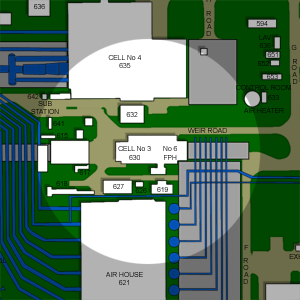
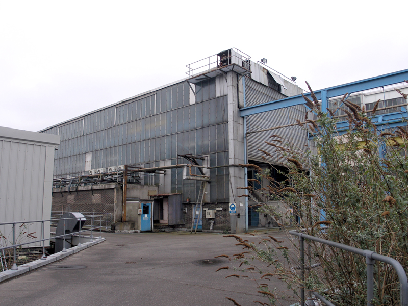
Cell 3, north western corner, as seen from Weir Road.
24|03|07 © Simon Cornwell 2007
|
Two buildings were constructed on top of this trench. The first was the main cell building which
covered the working section. This steel framed building was typical of the austere, functional
buildings of Pyestock. It was shuttered at its western end to allow gas turbines
to be winched into the loading bay and then lowered in a well which contained the working section.
The northern side was clad with glass to increase the natural lighting, whilst brick appendages
on the north and south sides provided space for workshops, storage space and control rooms for icing
tests.
A second building was constructed over another well which gave access to the exterior of the exhaust manifold.
This was little more than a metal frame with steel cladding over its northern and southern sides.
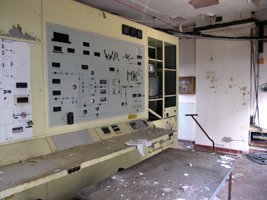
The main control room for the cell was housed in the Computer Building
over 700 meters away. A tunnel, called Monks Passage,
was constructed to provide a connection path between the control room and its cell.
|
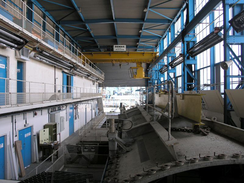
General view west across the whole of main external building of Cell 3.
24|06|06 © Simon Cornwell 2007
|
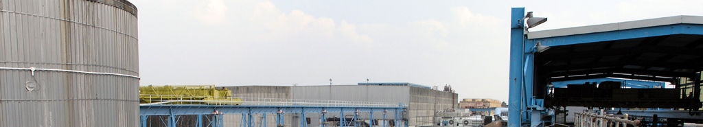
The cell was connected to the new air main and suction mains which were constructed along with the
Air House. It used the Air House (and later the
Parsons No. 9 and
No. 10 exhausters) to produce altitude conditions (unlike
Cells 1 and 2 which were driven by the ejectors). Compressed air was supplied by the
Air House only, whilst exhausting conditions could be produced by all the plant.
It could simulate altitude conditions to 70,000 ft. at mach 2.2, with temperature ranging from -70 through to
250 degrees.
|
|
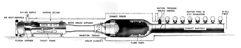
Cross-section of Cell 3 test plant
|
Temperature control was achieved by a separate heating plant (since removed), a separate cold air plant
(produced by a pre-cooler and pressure dryer system housed in a neighbouring building) and ice making
facilities (which could be found in the Cell 3 building). The four fuel systems connected to
the cell could also be varied and set to different temperatures and pressures. Additionally the GEC sets
could be configured to draw air through the Ceca Air Drying Plant
so tests could be conducted with dry air.
|
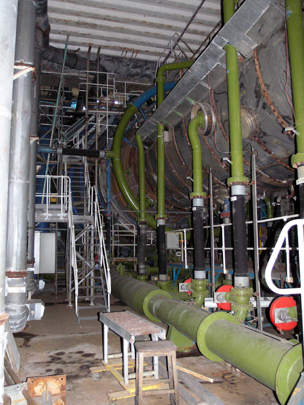
Piping and connections for the water cooled diffuser section. Looking west.
24|06|06 © Simon Cornwell 2006
|
Cell 3 became one of the most used cells of the site, its positioning within the air and
suction mains allowing a plethora of different connection strategies and options. Initially designed
for testing large diameter engines and combat jet testing, it was later used for military engine testing.
It could also be used for steady state performance measurement, control system evaluation, altitude
relighting, the limits of combustion stability, the evaluation of engine performance in severe
icing conditions and the tolerance to distorted inlet flows.
It only closed in 2002 when it was determined obsolete after over forty years of service. But its
working life wasn�t quite over and the working section was dressed up for the feature film Sahara
where the cell doubled-up as part of a futuristic toxic waste disposal facility.
Cell 3 Walkthrough...
Further Reading
|