|
The Buildings
home | the buildings | cell 4 (635)
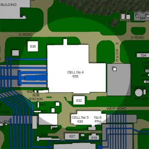
Cell 4 (635)
Built: 1965
Decommissioned: 1980
Cell 4 was an integral part of the massive supersonic-testing expansion of Pyestock,
as the need to test engines in close association with their air intake systems was an urgent requirement for
this new generation of aircraft. This could only be achieved by full-scale free-jet testing and
Cell 4 was designed to provide that capability. Therefore the cell could provide a means of
observing on the ground the interaction of the intake and engine combination at changing altitudes, Mach number
and incidence.
The cell was constructed in 1965 for Ł6.5 million in the north-western corner of the site, in close proximity
to the newly built Air House where it was directly delivered air from the
GEC compressor sets and indirectly via the Ceca air dryer.
|
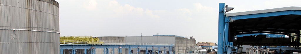
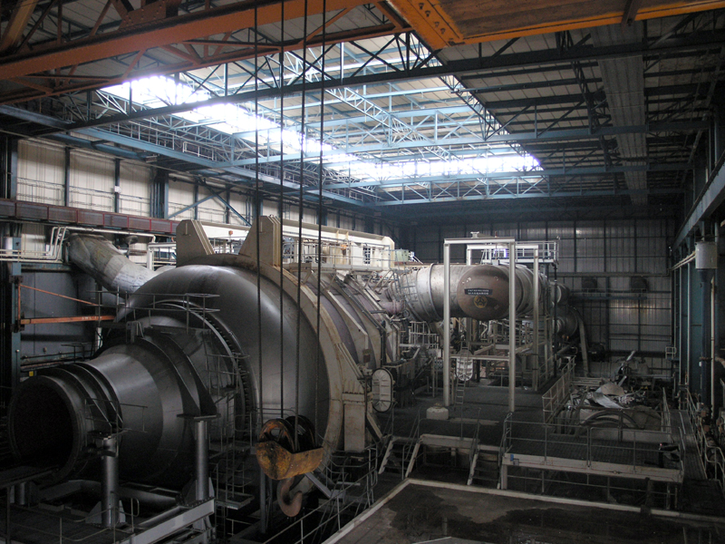
Cell 4, south east aspect, as seen from the elevated section of Weir Road.
05|05|07 © Simon Cornwell 2007
|
The cell was the largest testing cell built at Pyestock. Its total length of 400 feet included
many specialised sections: there was the 30ft-diameter 36ft-long inlet plenum chamber with its supersonic
blowing nozzle, a 10.5ft–long working section, a 10ft-diameter 16ft long engine chamber, a 55ft-long exhaust
diffuser, 160ft-long first and second stage coolers and finally 105ft of ducting at the rear to accommodate
seven GEC exhauster connections.
This was all housed in a huge brick and steel shed which was designed and constructed by the
Ministry of Public Buildings and Works (MPBW). The partly basemented building included the cell in one
massive room along with offices and control facilities in the brick wing on the south side of the main shed.
|
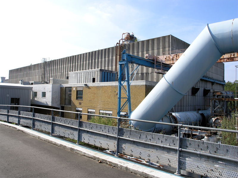
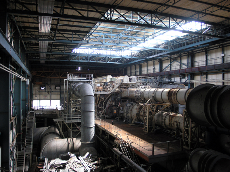
South-westerly elevated view across Cell 4.
24|03|07 © Simon Cornwell 2007
|
The fuel system was teed off the complimentary Cell 3, so both cells could not be
run simultaneously. 100 gallons per minute of fuel could be pumped to the engine under test whilst 200
gallons per minute were available for the reheat systems if desired.
Flight speed was simulated by two different supersonic blowing nozzles which had adjustable throats
and wall contours to provide variable Mach number operations. The total weight of the nozzle and moving
chamber assembly was 75 tons. One measured 25 square feet whilst the other was 20 square feet. They would
be positioned in the plenum chamber during testing.
|
|
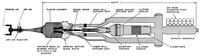
Cross-section of Cell 4 test plant
|
The heat exchanger to cool the engine exhaust was a major design consideration and plant item. The cooler
had two stages. The first stage cooler had six flame torches to ignite any unburned fuel in the engine exhaust.
The exhaust gases were at 1700°C at this stage where they would enter the first cooler where they were cooled
to 1000°C by a gas-over-tube-matrix which required a water flow of 620,000 gallons per hour. In the second
stage cooler, the gases passed through tubes in the conventional manner, and the temperature of the gases
was reduced to 150°C, which again required a similar amount of water. Water sprays were used in the final
section to reduce the gas temperature to 50°C which was the maximum allowable to return to the GEC exhausters.
Excess water drained into a 40ft deep barometric well.
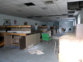
The main control room was located in the ground floor of the brick built extension. All test results were
fed to the SDS 9300 computer with its PDP7 in support. Back-up photographic recording equipment was also
available. Instrumentation permitted 300 pressure and 200 temperature points to be measured during steady-state
processing. Twenty-eight channels of magnetic tape, thirty-six channels of U.V. recording and digital counters
for engine speed and fuel flow were available for transient conditions.
|
Back section of Cell 4 including the diffusers, coolers and flame traps.
24|06|06 © Simon Cornwell 2006
|
Shortly after its construction, the cell was modified to enable it to fly the Rolls-Royce Olympus 593 which
was being developed for Concorde. The cell’s abilities were enhanced to be able to fly at Concorde’s
cruise parameters of Mach 2 at 61,000 feet. To enable this, further exhaust capacity was installed as
Number 9 Machine; and extra spill diffusers, mounted above and below the intake,
were used to obtain the altitude conditions in the working section. Extra ductwork was added to accommodate the
"ramp bleed" and "dump floor" flows which were an essential feature of the Concorde aircraft power plant.
After the successful Concorde trials, the cell was used for general free jet testing in supersonic mode and
for subsonic free jet testing of the engine and intake. However, the cell was limited to investigations
of aerodynamic compatibility of the intake/engine combination and was never used to test performance
(unlike the complimentary Cell 3). With the decline of supersonic projects
and its specialised, power-hungry needs, Cell 4 was surplus to requirements
and was mothballed in the 1980s.
Cell 4 Walkthrough...
Further Reading
|