 | Air Supply Installations |
3. N.G.T.E. Air Supply Installations
The main feature of the air supply equipment installed at N.G.T.E. is that where necessary the machinery
can compress atmospheric air to high pressure before it is pumped to the experimental test cells and rigs, or
alternatively, the machines can be set so that they suck away or exhaust the test cells and in so doing create
altitude effect by reducing the working pressure in the rig below the barometric value.
When the same machines are used to perform either the compressing or exhausting duty there is
a considerable saving in capital costs. However, some plant is installed for a single purpose, the precise role
being dictated by the evolution of the aircraft development programme which determines the capacity of
compressed air and exhauster throughputs. The amount of flow for each duty is reviewed as new aircraft engine
requirements arise.
Air machinery is the predominant factor in all gas turbine research and the special installations
at the N.G.T.E. provide an exclusive service that can be offered by the Establishment to
Industry.
The limit placed on performance by the output of machinery is usually one of the main factors
in deciding the maximum flight speed, altitude and/or the size of the engine that can be tested in the different
test cells.
Because there is often a need to simultaneously supply a matched blowing and sucking service to
a test cell performing at altitude, the practise used particularly in the N.G.T.E.
Air House of combining the two duties in one machine is most significant
in stretching the plant operating range.
Also it helps test programming considerably during plant maintenance periods if equipment can be
switched from one role to another.
Altogether, there are eight separate installations making up the total Air Supply service at
N.G.T.E.. These are all individually listed in Tables I and II. The former lists the New Site, and the latter,
the Old Site installations.
Table I
Air Supply and Extract Plant - N.G.T.E. New Site
| Air House |
General Electric Co. (GEC) 9:1 Pressure ratio |
8 |
Compressing and exhausting |
| No. 9 machine Building |
Parsons 1:13.6 Pressure ratio |
1 |
Exhauster only for Cell 3,
Cell 3 West and
Cell 4
|
| No. 10 machine Building |
Parsons 1:9 Pressure ratio |
1 |
Exhauster only for Cell 3,
Cell 3 West and
Cell 4
|
| Plant House |
Metropolitan Vickers 6:1 Pressure ratio |
2 |
Compressing and exhausting |
| Parsons Air Bleed 4:1 Pressure ratio |
1 |
Compressing only |
| Reavell 2½:1 Pressure ratio |
1 |
Compressing only |
| Holman Low Flow 10:1 Pressure ratio |
1 |
Compressing only. Service for auxiliary plant. |
Table II
Air Supply Plant - N.G.T.E. Old Site
Old Site
Compressor
Hall |
B.T.H. 4:1 Pressure Ratio |
1 |
All machines
act as
compressors
only |
| Demag 4:1 Pressure Ratio |
1 |
| Demag 10:1 Pressure Ratio |
1 |
| Lysholm 3:1 Pressure Ratio |
1 |
| Alley 30:1 Pressure Ratio |
1 |
| Holland Exhausters |
2 |
Exhausters only |
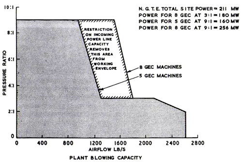
The combined performance of the N.G.T.E. air machinery is shown in Figures 4 and
5. The former shows the total blowing capacity if all the Air House G.E.C.
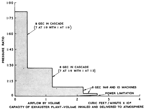
machines are used together as compressors, whilst the second figure shows the maximum exhauster capacity
over the whole sub-atmospheric pressure range if all the New Site air machinery is combined together to operate as
exhausters.
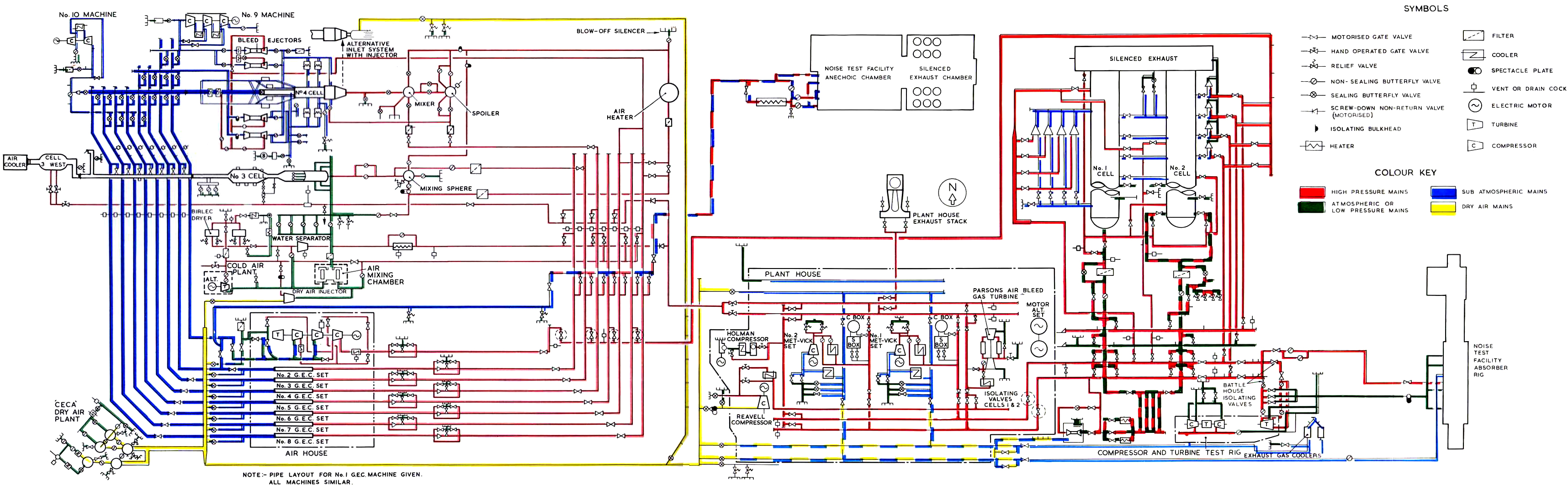
The air machinery connects with associated air processing plant such as air dryers, heaters,
cold air plant, etc. and the test cells by way of large diameter pressure network. These connecting mains form an
integrated network for supplying the different test cells and component testing laboratories with a wide variety of
different services. The complete air main complex is shown diagrammatically in Figure 6 whener the code
reference indicates the pressure, vacuum or dryness conditions that is available in the vairous flow circuits. The
diagram also indicates the manner in which the pipes to different test facilities are interconnected with each
other; this arrangement is a deliberate feature of the Engine Test Facility network which gives a wide operational
flexibility. However, the interdependence of the cells and test laboratories on a network with so many flow
routes makes test programming essential so that tests do not interfere with each other. Generally N.G.T.E.
operate a rota procedure which permits each test plant to have testing priority in turn and air bookings are arranged
accordingly. Safety procedures guarantee that all valves are correctly set according to the particular requirements
of the tests and the appropriate safety instructions are put into effect before, during and after every test.
This vital step is aimed at protecting personnel working in or around sections of the pipework system not involved
in the test, as well as safe-guarding expensive plant which could be damaged if it were not isolated.
|
|
Fig. 4 Total blowing performance of the N.G.T.E. Air House - 1969
|
|
|
Fig. 5 Combined exhauster performance of N.G.T.E. plant - 1969
|
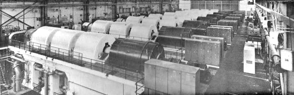
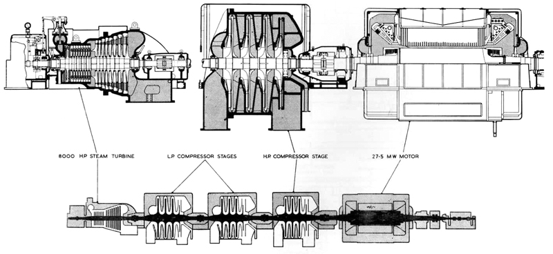
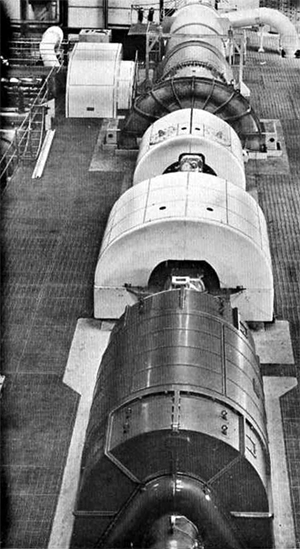
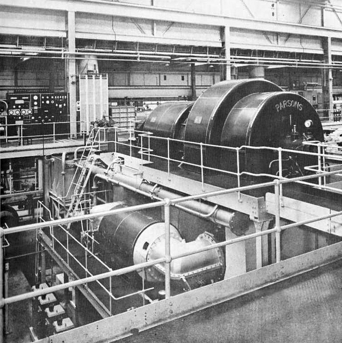
4 Air House GEC Compressor/Exhauster Machinery
(Eight similar units installed - Machines 1 to 8)
Each of the eight G.E.C. compressor/exhauster sets consists of three 3:1 centrifugal
compressor stages mounted in line with a 27½ megawatt (36,500 horse-power) electric motor at one end of the
connecting shaft and an 8,000 horse-power steam turbine at the other end. The steam turbine is used to start and accelerate the machine to its constant running
speed of 3,000 rev/min. This is acheived with the compressor inlet air valves set (1:9 exhausting) to
keep the power load within the 8,000 horse-power limit. At the design speed the electric motor is
synchronised with the Central Electricity Board grid frequency and the combined power from the electric
motor and the steam turbine is available to meet high load conditions. Figures 7 and 9 illustrate
the G.E.C. machines in detal.
According to pre-arranged valve settings the G.E.C. plant can be used to pump
high pressure air to the engine installation or to evacuate the test chamber to produce altitude conditions.
The three 3:1 compressor stages of a G.E.C. machine can be run in parallel to give
air throughput conditions at 3:1 pressure ratio; alternatively, two stages of the machine can
be arranged to run in parallel supplying the third stage in series to give a proportionally lower flow
at 9:1 pressure ratio. When run as exhausters, pressure ratios of 1:3 and 1:9 can be achieved in the
same way.
When extreme altitude conditions are required it is possible to run seven
G.E.C. machines in parallel feeding the delivery flow to the other G.E.C. set running in serious
operation and thus obtain pressure ratios down to 1:81 of atmospheric pressure. A special crossover
main is installed for this purpose but only No. 1 or 2 G.E.C. sets can serve as the series
operated machine. Figure 5 shows the total performance of the G.E.C. machines when used in this
cascade type of operation both when the seven machines are set to 1:3 cascading into an eighth machine
set at 1:9 to give an overall pressure ratio of 1:27 and also when all
machines are set to 1:9 pressure ratio (1:81 total).

|
|
Fig. 6 N.G.T.E. Air Distribution Network
|
|
|
Fig. 7 Air House G.E.C. 3-stage compressor/exhauster machine
|
Table III
Design Output of G.E.C. Compressors at 3:1 and 9:1 Pressure Ratio
Individual Machine Output
| Air mass flow lb/s |
295 |
200 |
| Nominal shaft power hp |
30,000 |
43,000 |
| Delivery temperature range °C |
50 to 150 |
70 to 225 |
| Exhauster inlet pressure inch Hg abs |
9 |
7.5 |
6.0 |
4.5 |
3.5 |
3.0 |
2.75 |
| Air mass flow lb/s at 15°C |
72 |
58.3 |
47.3 |
34.0 |
23.7 |
18.0 |
14.0 |
| Inlet temperature range °C |
20 to 75°C |
Mass flows are reduced by at least 10 per cent when the inlet temperature
is increased to 75°C
|
The nominal design output of the G.E.C. plant under 3:1 and 9:1 pressure ratio operation
is given in Table III.
Eight similar G.E.C. machines are installed, all of which can compress or exahust according
to test requirements. Naturally the power consumption falls in proportion to the inlet air density when
the machines act as exhausters and the power may be shared between the steam turbine or electric motor
to give the best economy or most convenient running situation.
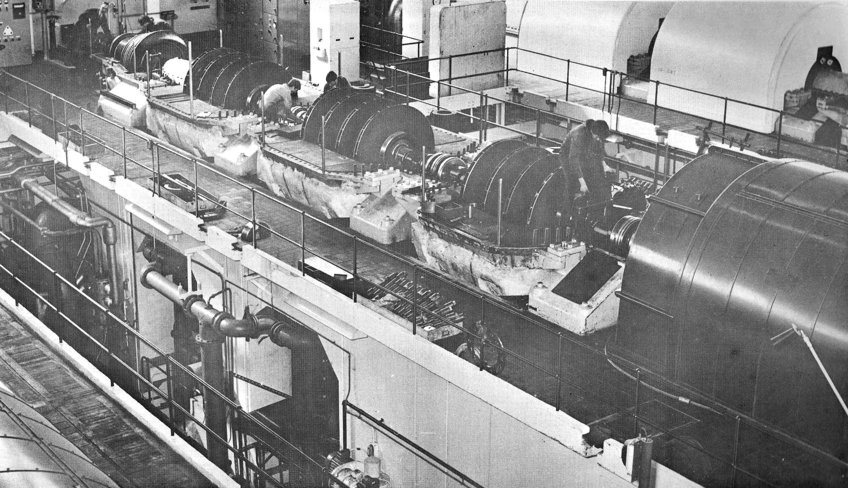
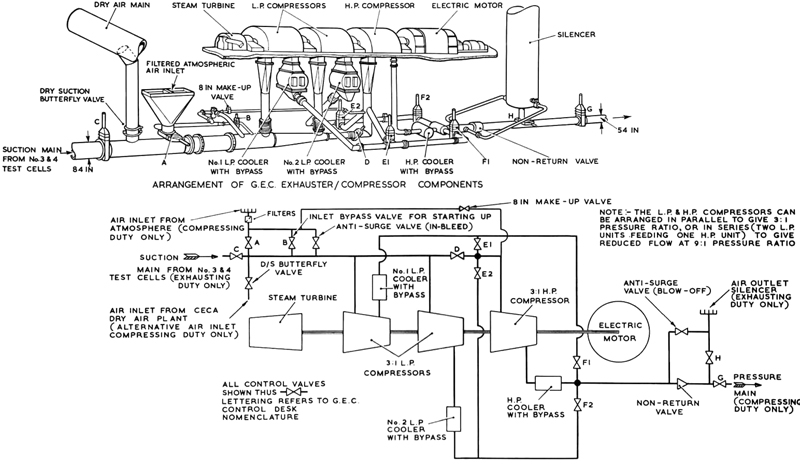
Figures 8 and 9 indicate the in-line arrangement of the G.E.C. machinery together
with the air circuit diagram; also the positions in the circuit of the air coolers, inlet air filters, valves
etc., are shown as well as the position of the atmospheric exhaust silencer stack.
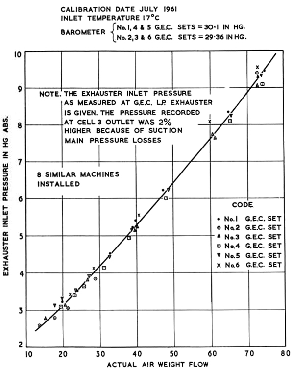
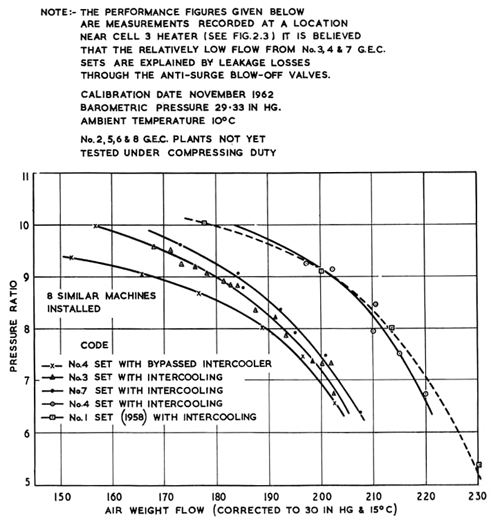
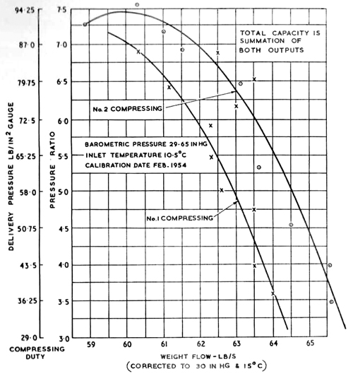
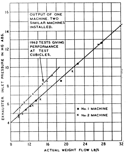
The performance of individually tested machines is given in Figures 10 and 11, both as compressor and
exhauster plants. As compressors, some discrepancy in airflow existings between the different sets but it
is known that air leakage occurs at various points in the compressors and their pipework, e.g. in
valves, glands, pipejoints, etc; This explains the variations in performance. Under suction conditions
there is less variation and output between sets is more uniform. N.G.T.E. are prohibited
by operational costs (�280 per hour without capital depreciation allowance) from conducting frequent
routine performance calibrations of the G.E.C. sets.
No. 1 and 2 G.E.C. sets have a separate electric power supply fed directly from the C.E.G.B. sub-station through
two 20 megavolt ampere cable feeders as shown in Figure 18 and described in Section 6,
it is advisable to note this particular arrangement when programming tests during electrical maintenance periods and/or
periods of restricted electrical load in case these two machines are out of service.
The machines have damper controlled aftercoolers permitting temperature control from
40°C to 130°C at the 3:1 condition or 60°C to 220°C at 9:1 condition.
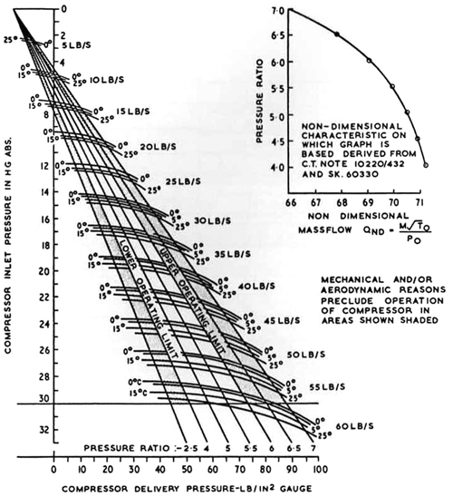
Anti-surge regulartors protect the machine under all operating conditions. Figures 12 to 16
show the various parts of the Air House equipment.
|
|
Fig. 8 Air circuit for a G.E.C. exhauster/compressor installed in Air House
|
|
|
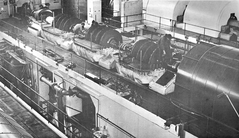
Fig. 9 G.E.C. exhauster/compressor set; top half casing removed.
|
|
|
Fig. 10 Performance of Air House G.E.C. plant at 9:1 pressure ratio working as a compressor.
|

|
|
Fig. 11 Performance of Air House G.E.C. plant at 1:9 pressure ratio working as an exhauster.
|
|
|
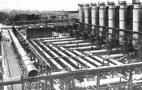
Fig. 12 General view of Air House compressor delivery plant and atmosphere exhaust stacks.
|
|
|
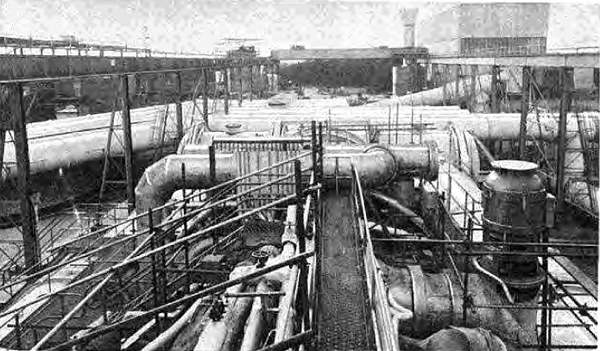
Fig. 13 G.E.C suction mains and No. 10 exhauster building.
|
|
|
Fig. 14 Side view of G.E.C. compressor plinth showing intercooler units, etc.
|

|
|
Fig. 15 The Air House G.E.C. plant hall.
|
|
|
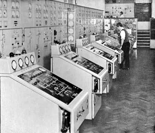
Fig. 16 The Air House control room showing six of the G.E.C. control desks, etc.
|
|
|
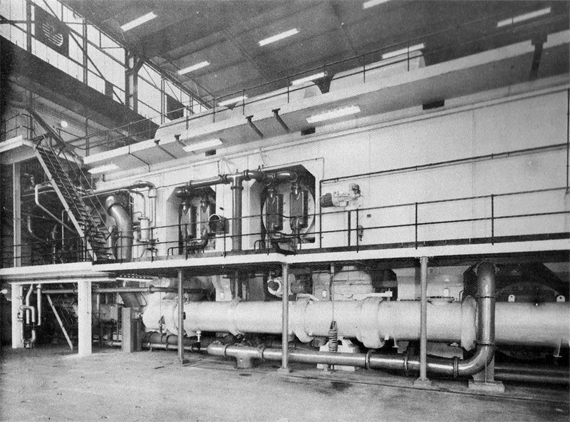
Fig. 17 No. 9 exhauster.
|
5. No. 9 Machine - Parsons Exhauster
The vast blowing capacity of the N.G.T.E. Air House
plant meets the requirements for present gas turbine gas turbine test programmes; however, the demand for suction
capacity constantly rises as engine size and range increase. To this end it has been necessary to increase
exhauster capacity beyond that originally installed on two occasions, first by installing No. 9 machine
and then No. 10. Both these machines were built therefore to
perform as exhausters only.
Considerations of pipework size and installation arrangements limits the use of the
Parsons No. 9 machine to Cell 3,
Cell 3 West and Cell 4. When
used to exhaust Cell 4, it exhausts the boundary layer bleed flow from
the air inlet working section whilst the Air House machines suck the
engine and free jet nozzle spill flows. No. 9 machine is housed in
a building adjacent to Cell 4 as shown in Figure 17.
No. 9 machine is a three stage axial exhauster will full intercooling between stages having
a compression ratio 1:13.5. The exhauster is driven by a 36,000 horsepower synchronous motor that is brough to the
constant operating speed to 3,000 rev/min by coupling the motor to a variable frequency electrical supply so that
the equipment is started as an induction motor.
The motor, working as induction unit, is brought up from barring speed to 600 rev/min with
current from the Bellis and Morcom steam turbine driven 12.75 megawatt alternator, described later in this brochure.
At 600 rev/min the motor is synchronised with the alternator so that as the
alternator speed is raised to 3,000 rev/min by the steam turbine, the motor is automatically raised with it.
At 3,000 rev/min the motor is synchronised with the electrical grid supply.
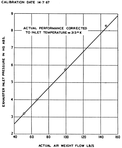
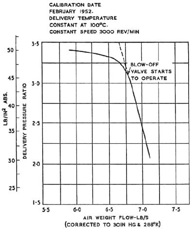
Table IV gives the design output of No. 9 machine
corrected to an inlet temperature of 313°K. The calibrated output of the exhauster is shown plotted in Figure 18.
Table IV
Design Performance of No. 9 Exhauster
| Inlet pressure lb/in2 abs |
1.1 |
5 |
| Overall pressure ratio |
1:13.5 |
1:8.6 output pressure 43 lb/in2 abs |
| Air weight flow lb/s |
36.3 |
165.5 |
| Power consumption megawatts |
7 |
23 |
| Inlet temperature °K |
313 |
313 |
|
|
Fig. 18 Performance of No. 9 exhauster plant.
|
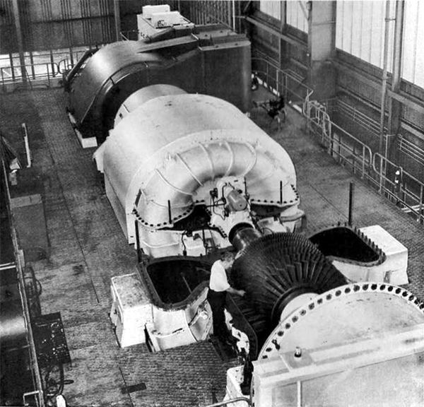
6. No. 10 Machine - Parsons Exhauster
The range of full scale free jet nozzle expansion tests that can be carried out at
N.G.T.E. has been further extended by the installation of a second Parsons axial exhauster.
This plant is similar in capacity to No. 9 machine although it
has a lower overall pressure ratio of 1:9 compared with 1:13.5.
The machine can be used instead of No. 9 when the
latter is being serviced or it can be used in parallel when maximum output is necessary. However, like
No. 9 machine,
No. 10 is limited to service for
Cell 3,
Cell 3 West and Cell 4.
The installation is illustrated in Figure 19.
No. 10 machine is a two stage axial exhauster driven
by a 25 megawatt synchronous induction motor. Starting is accomplished by a liquid starter in which
external resistances are reduced as rotor speed is increased.
The plant is connected to the E.T.F. exhaust main network by teeing into four of the vaccum mains
downstream of Cell 4 exhaust manifold, as shown in Figure 6.
The maximum temperature of the air sucked by No. 10
machine must not exceed 40°C.
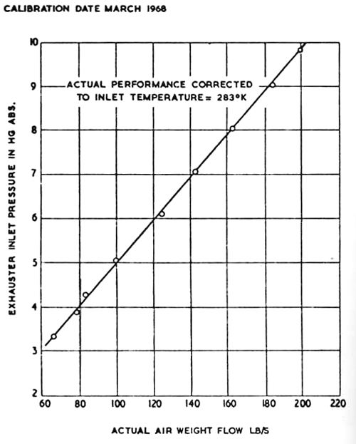
Table V gives the design output at maximum power and minimum working pressure corrected to an
inlet temperature of 283°K whilst Figure 20 shows the calibrated performance over the working range.
Table V
Design Performance of No. 10 Exhauster
| Inlet pressure lb/in2 abs |
1.635 |
5 |
| Pressure ratio |
1:9 |
1:5 |
| Air weight flow lb/s |
69 |
208 |
| Power consumption megawatts |
9 |
25 |
| Inlet temperature °K |
283 |
283 |
The power consumption of both No. 9 and
No. 10 machines is given in Figure 20. In both cases the
machines are not operated at inlet pressures between 5 and 14.7 lb/in2 abs. because of the
power limitations on the driving motor.
|
|
Fig. 19 No. 10 exhauster.
|
|
|
Fig. 20 Performance of No. 10 exhauster plant.
|

|
|
Fig. 21 Power requirements of No. 9 and No. 10 exhausters.
|
7. Plant House Machinery
There are four alternative air supplies installed in the Plant House,
they are:-
- Two Metropolitan-Vickers 6:1 compressor/exhausters
- A Reavell 2½:1 compressor
- A Parsons 4:1 air bleed gas turbine
- A Holman 10:1 low flow compressor
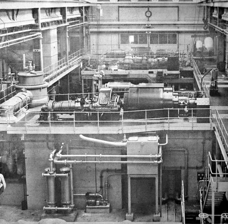
8. The Metropolitan-Vickers 6:1 axial flow compressor/exhausters
The two Metropolitan-Vickers Plants, having a nominal maximum rating of 8,850 horse-power each on
compressing duty, provide the main Plant House service. The plant
is shown in Figure 22.

|
|
Fig. 22 The Plant House Metropolitan-Vickers machinery.
|
Table VI gives performance of one Metropolitan-Vickers set, a more detailed analysis of
the performance as measured in experimental tests at N.G.T.E. is presented in Figures 23 and 24.
Each Metropolitan-Vickers compressor is driven by a synchronous electric motor which is started as an induction
motor and switched by the auto-transformer method to operator as a synchronous motor once the rotor has
reached a speed of 1,000 rev/min. The compressor is driven through a helical gearbox of 7.15:1 speed ratio
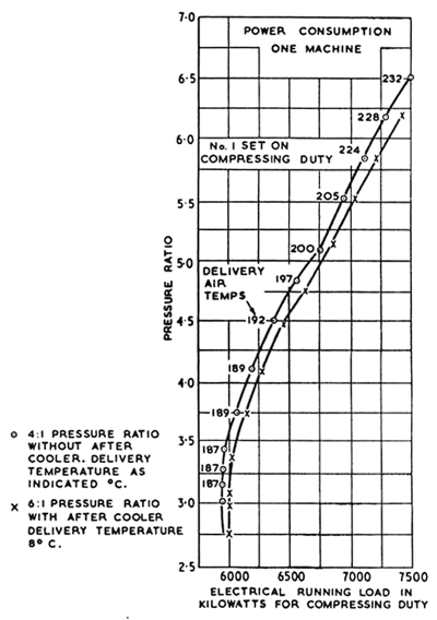
so that the constant compressor rotor speed is 7,150 rev/min. The operating range and power demand is shown
in Figures 25 and 26.
There is a damper controlled after-cooler which permits temperature control between 30°C to
245°C if the machine operates as a compressor. When operating as an exhauster a precooler is in circuit to
reduce the air inlet temperature from a maximum of 250°C to below 50°C.
Anti-surge regulators protect the machine under all operating conditions. It is not desirable
to run the machines at pressure ratios less than 4:1.
Table VI
Performance of Metropolitan-Vickers Compressor/Exhauster
Individual Machine Output
| Delivery pressure ratio |
4:1 |
5:1 |
6:1 |
| Air mass flow lb/s |
63.5 |
63 |
62 |
| Shaft power hp |
6400 |
6700 |
7500 |
| Delivery temperature range °C |
30 to 245 |
| Exhauster inlet pressure inch Hg abs |
14 |
12 |
10 |
8 |
6.0 |
4 |
| Air mass flow lb/s at 15°C |
30.5 |
26 |
21.8 |
17.5 |
12.5 |
8 |
| Inlet temperature range °C |
Not to exceed 50 |
|
|
Fig. 23 Performance of Metropolitan-Vickers plant as compressors.
|
|
|
Fig. 24 Performance of Metropolitan-Vickers plant as exhausters.
|
|
|
Fig. 25 Operating diagram for Metropolitan-Vickers exhausters/compressors.
|
|
|
Fig. 26 Power consumption for Metropolitan-Vickers compressors.
|
9. The Parsons Air Bleed, Reavell and Holman Machines
The Parsons, Reavell and Holman plants are restricted to
compressor duty and do not provide an exhauster service. The Parsons 4:1 air bleed gas
turbine has a maximum ouput of 25 lb/s with an air temperature range of 70°C to
180°C, and consists of a compressor, two combuston chambers, turbine and aftercooler.
It has a simple open cycle and develops a total shaft horsepower of 2710 at the
design speed of 4,600 rev/min. The plant is shown in Figure 27.
The output weight flow is bled from the compressor delivery
ducting and discharged into the Plant House
test rig bus mains.
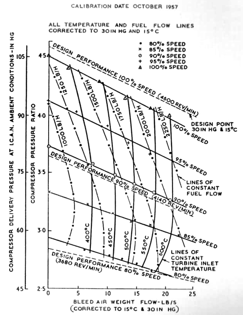
The performance envelope for the Parsons air bleed gas turbine is given
in Figure 28.
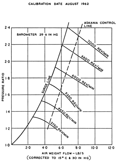
The Reavell compressor is installed to give a service supply for model
rig tests when high pressures are not essential. The output performance of this plant is
given in Figure 29; nominally it should produce 8 lb/s at a pressure ratio of 2.5:1, however,
the diagram shows that the calibrated performance is slightly less. The compressor is electrically
driven by a variable speed induction motor of 600 horse-power; no aftercooler is fitted and the
air delivery temperature therefore increases with pressure.
The 105 horse-power electrically driven Holman compressor has only an output
of 0.5 lb/s but is able to deliver this flow at 10:1 pressure ratio and is useful for a
variety of tests relating to combustion research.
|
|
Fig. 27 The Parsons air bleed gas turbine.
|
|
|
Fig. 28 Performance of Parsons air bleed gas turbine.
|
|
|
Fig. 29 Performance of Reavell 2.5:1 centrifugal compressor.
|
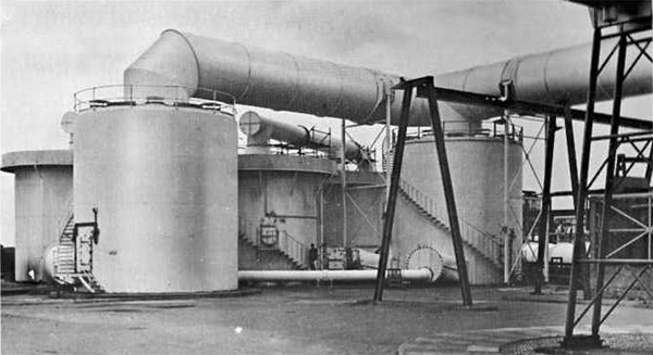
10. N.G.T.E. Old Site Air Supply Installation
All the facilities described so far have been developed since 1950 in the newer part of the Establishment.
However, in addition N.G.T.E. still retains in service the older installations built earlier on the original part of
the Establishement known as the Old Site.
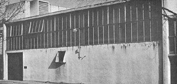
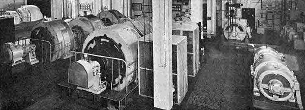
The Old Site machinery is self contained and is housed in its own Compressor Building supplying a number of
independent laboratories which house various combustion chamber component test rigs and aerodynamic wind tunnels
although full scale engine tests are not possible. The compressor building is shown in Figure 30 and the plant in
Figure 31.
|
|
Fig. 30 Old site compressor house.
|
|
|
Fig. 30 Old site compressor hall.
|
The old site air plant is mainly a compressed air supply with little exhauster capacity.
The compressed air supplies are as follows :-
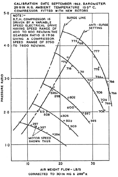
- B.T.H 4:1 compressor having a capacity of 28 lb/s with a compressor deliver temperature range of 20° to
180°C. The detailed performance of this compressor is given in Figure 32. The special advantage of this compressor
is that it is driven through a Ward-Leonard motor generator set which allows it to be run over a very wide speed
range from 3,750 rev/min up to the design rotor speed of 7,500 rev/min.
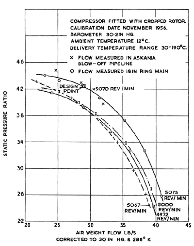
- A 4:1 Demag compressor having an air pumping capacity of 32 lb/s, with a delivery temperature range of 20°
to 180°C. Figure 33 shows the performance of this compressor. The electric motor is able to give a limited
speed range from 5,250 rev/min down to 3,750 rev/min.
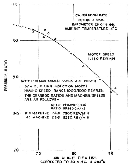
- A Demag 10:1 compressor which can supply 7½ lb/s at 10:1 compression ratio, the delivery flow increases
to 9 lb/s if the compression ratio is reduced to 8.7:1. This machine has a constant air outlet temperature of
95 to 100°C. The performance at the design speed of 1,450 rev/min is given in Figure 34.
NOTE: The 4:1 and 10:1 Demag compressors described are arranged at opposite ends of the same double output-shafted
4,000 horse-power electric motor, and in consequence only one of the compressors can run at the same time and machine
coupings much be changed over before the compressors can be switched.
- A Lysholm 3:1 compressor ratio plant which delivers 6.6 lbs/s at a constant delivery temperature of 100°C
and which has the compressor characteristic shown in Figure 35.
- An Alley 30:1 three stage reciprocating compressor which can supply 0.5 lb/s. The outlet flow from the
compressor is cooled to a maximum temperature of 24°C and dried to the dewpoint corresponding to a temperature
of -40°C. The dryer is continuously rated; alternate driers are switched on line after automatic
re-activation.
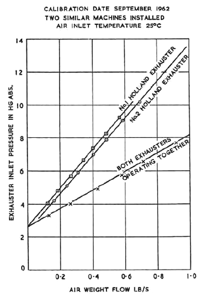
Although most of the tests on the Old Site are at sea level static conditions, minor exhauster
equipment is installed. This consists of two Holland type exhausters which, when operating together, can suck
1 lb/s at an inlet pressure of 8 in Hg abs reducing to ½ lb/s when the inlet pressure falls to 5.4 in Hg abs
and 0.25 lb/s at 4 in Hg abs. The complete characteristics for both of the individual Holland exhausters, as well
as the flow available when both operate together, is given in Figure 36. The exhaust gases from all test rigs
must be cooled to 40°C before they can be sucked through the Holland exhausters.
Dry air can be induced by ejectors into No. 6, 13 and 14 old site laboratories, the air
being drawn through a silica-gel bed. The bed will dry 2lb/s for approximately three hours to the dewpoint corresponding
to a temperature of -20° before re-activation is necessary.
|
|
Fig. 32 Performance of BTH 4:1 compressor.
|
|
|
Fig. 33 Performance of Demag 4:1 compressor.
|
|
|
Fig. 34 Performance of Demag 10:1 compressor.
|
|
|
Fig. 35 Performance of Lysholm 3:1 compressor.
|
|
|
Fig. 36 Performance of Holland exhauster plant.
|
11. Dry Air Facilities (a) The Ceca Plant
When the Air House and
Plant House machines are on compressing duty, they normally draw
their air supply from the atmosphere. However, if desired and excepting the Air Bleed Gas Turbine, any compressor
can be connected to an atmospheric air drying plant manufactured by the British Ceca Co. Ltd. so that the
engine under test can be supplied with dry air.
Some test rigs working at or below atmospheric pressure bypass the
Air House compressors and draw their air direct from the dryer
using ejectors or exhausing plant to induce the air-stream. Test Cells 1 and 2
described in paragraph 13 are a particular example of rigs that may operate in this way.
Figure 6 shows the relative location of the air dryer plant and associated pipework circuit
which allows dry air to be supplied to
Cell 1,
Cell 2,
Cell 3,
Cell 3 West,
Cell 4 and the
Noise Facility, as well as the aerodynamic and
combustion laboratores. The plant itself is shown in Figure 37
|
|
Fig. 37 The Ceca dry air plant.
|
The complete Ceca dry air facility consists of two individual plants which together contain 162
tons of silica gel; the two units can operate singly or in parallel. One plant contains two adsorber veseels which together dry a maximum of 400 lb/s
of air throughput, while the second plant having only one adsorber vessel is limited to 200 lb/s capacity at the present time. Provision has been made in the
second plant for the possible addition in the future of a futher adsorber vessel also of 200 lb/s throughput, which will thus increase the capacity of the
second plant up to the output of the first. The total capacity of the
Ceca dryer is therefore 600 lb/s at present, but thsi could easily be increased to 800 lb/s if and when the extra
adsorber vessel is built.
One of the benfits that arise from the existence of two separate plants is that one unit may be re-activated, whilst the other
is providing an adsorbion service. The time taken to re-activate depends on the amount of moisture adsorbed, but it never exceeds a maximum time of
9 hours.
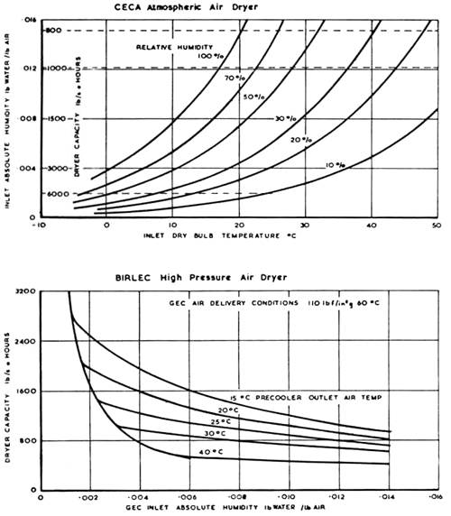
The performance of the Ceca dryer plant
is given in Table VII together with that for the Birlec dryer.
(b) The Birlec Dryer (Cell 3 Cold Air Plant Route)
In order to boost the dry air for the Cell 3 cold air
plant described in Section 3, Paragraph 6, a second dry air plant using 30 tons of silica gel has been installed.
The casings of the dryer vessels of this plant, which was manufactured by Birlec Limited, have
been designed to withstand high internal pressures so that compressed air delivered from the GEC 9/1 or Metvick 6/1
compressor/exhausters many be processed. The Birlec dryer may be used in series with the Ceca plant to maximise dryness
ratio, or alternatively to stretch the time duration between re-activating periods. However, when required, the Birlec
dryer may be used on its own using various flow routes depending on the location of interconnecting pipe manifolds and/or
control valves. The flow routes to various test cells, the
Noise Facility or
Plant House test rigs, may be traced using Figures 6 and 55 together.
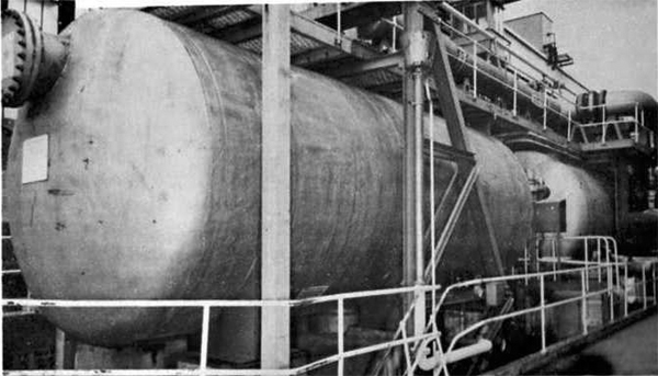
A general view of the Birlec dryer is shown in Figure 38.
|
|
Fig. 38 General view of Birlec dry air plant.
|
|
TABLE VII
Performance of N.G.T.E. Air Drying Plant.
|
The Birlec HP dryer consists of a water-cooled shell and tube heat exchanger
designed to cool 200 lb/s of air at 12 atmospheres pressure absolute from 70°C to 32°C
and a water separator to centrifuge out free moisture carried along in the airstream, two pressure vessels holding
beds of activated alumina and an outlet filter assembly. The dryer was designed to process 200 lb/s of air from saturation
at 35°C to an absolute humidity of 0.0002 lb of moisture/lb air (frost point -10°C) for a period
of 2 hours.
The duration of adsorption period and final humidity depends upon air flow rate,
inlet air humidity and temperature, consequently a family of curves are used to predict dryer performance
and these are given in Figure VII for particular GEC compressor/exhauster delivery conditions.
© Procurement Executive, Ministry Of Defence
|