 | Component Test Facilities |
24. Component Test Installations
It is not always essential to conduct gas turbine research by the complete full scale testing
of the whole engine and there are many advantages to be gained from the technique of testing individual components
in specially designed rigs. Much of the work of the National Gas Turbine Establishment is performed by making
rig equipment which can be designed so that the particular problem under review is isolated from side effects,
thereby permitting development work to proceed more swiftly. Also, research is far less expensive when component
or model tests replace full scale engine tests.
In addition to the five E.T.F. cells, the facilities at N.G.T.E. include experimental laboratories for
the rig testing of gas turbine compressors, turbines, combustion chambers and exhaust systems. Altogether, there are
four separate facilities for component testing, firstly there is the original compressor plant and test cubicles
built on the 'Old Site'; this early installation is still in continious service and its compressor machinery is described
separately in para. 10. On the N.G.T.E. New Site there is the Plant House
aerodynamic and combustion rigs which derive their air supply from the Metropolitan-Vickers compressor/exhausters,
the Battle House compressor and turbine test beds, and the
Admiralty test house in which naval gas turbine components are tested.
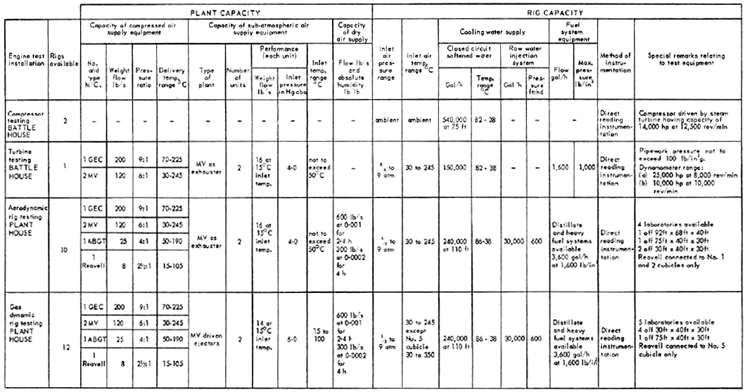
The performance capability of the New Site rig facilities are summarized in Table 12, the Old Site test rig
facilities are described in para. 29.
The major requirement of all rig and component test installations is the availablity of a high
pressure air supply and therefore the Plant House and
Battle House component test beds are cross linked with the compressor/exhauster
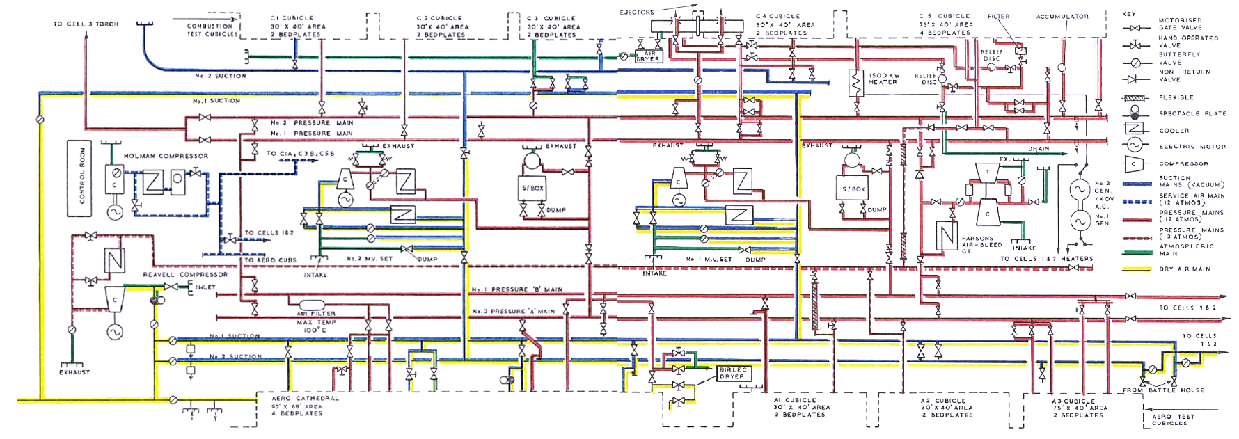
machinery installed for engine testing. Figure 6 shows diagrammatically the details of these interconnections.
25. Compressor Testing Facilities
The flexibility introduced by the technique of component testing in gas turbine research has already
been stressed. This is particularly so when considering the development of the compressor and turbine components. These
units comprise the main rotating parts of a gas turbine engine and whereas it is sometimes desirable to conduct tests
on individual blades and blade segments usually referred to as cascades, frequently it is preferable to experiment on
a complete compressor or turbine assembly.
Major facilities for testing these major gas turbine components are provided in the building known
as Battle House, where the Establishment's high pressure steam output is
also generated. The location of the two plants in close proximity are particularly arranged in order to reduce the
pressure and temperature losses in the circuit supplying steam to the turbine which is used to drive the experimental
compressors. This steam turbine was specially designed and manufactured by the Brush Company Ltd., to operate over
a wide range of operating conditions, it is capable of driving compressors of up to 14,000 horse-power at rotational
speeds not exceeding 12,500 rev/min, using a steam supply of 400 lb/in2 and 650°F (343°C), the maximum
steam demand being 185,000 lb/h. The turbine itself is double-ended, thus two experimental compressors can be installed
on the test bed at the same time; however, it is important to realise that with this design concept the direction of rotation
of the experimental compressors must be chosen to suit the installation arrangement; make-up shafting between the steam
turbine and the experimental compressor allows either rig to be quickly coupled ready for running, although blanks must be
fitted to the non-running compressor to prevent windmilling.
Table XII
N.G.T.E. NEW SITE COMPONENT TEST RIG FACILITIES

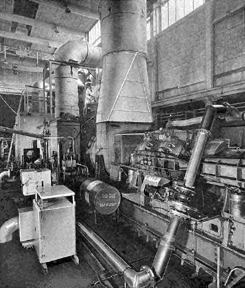
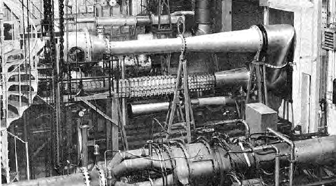
Figure 84 shows the bed with two engine compressors installed, the unit
on the far side being coupled to the turbine. The test bed is provided with its own
fully instrumented control rooms for controlling and measuring the steam turbine speed
and to give direct reading of experimental data from the test compressor, also a
data aquisition unit scans pressure and temperature readings and produces punched
tape ready for computer processing.
|
|
Fig. 84. The Brush steam turbine installation, used for compressor testing, showing experimental
compressors in situ.
|
The test compressor normally draws its air direct from atmosphere through a low-loss silenced
intake of 250 lb/s capacity and a calibrated measuring section, while the exhaust is normally led to a low-loss
exhaust silencer. However, it is possible to route the output from the test compressor to the turbine hall
where the temperature is increased in a combustion chamber before it is used to drive the experimental turbine;
this technique allows a compressor and turbine to be tested together as a matched pair.
26. Turbine Testing Facilities
Turbine component testing takes place in a test hall adjacent to the compressor rig where the plant
has been planned so that experimental turbines together with their associated combustion systems can operate using
air from the Establishment's compressed air supply, this is the normal testing arrangement but if necessary air
may be drawn from the experimental compressor on test in the compressor hall. Figure 6 shows the manner in which
the compressed air is routed from the G.E.C. or Metropolitan-Vickers compressors to the turbine test rig, the pipework
between the Cells 1 and 2 pressure mains and the
Battle House being 24 in. in diameter. As
Cells 1 and 2 pipe network is used to convey the pressure air through
to the turbine test rig, turbine tests must be programmed so as not to clash with those in these cells.
The turbine component is usually put under test with its associated combustion system and consequently the
exhaust system is designed to handle hot gases and splitters are fitted to provide suitable noise silencing; the inlet
ducting is fitted with 20 in. diameter I.S.A. nozzle for measuring airflow.
If desired, the experimental turbine can be tested under altitude conditions by using the Metropolitan-Vickers
6:1 exhausters to suck the turbine exhaust through two 48 in. suction mains which are connected to the exhauster
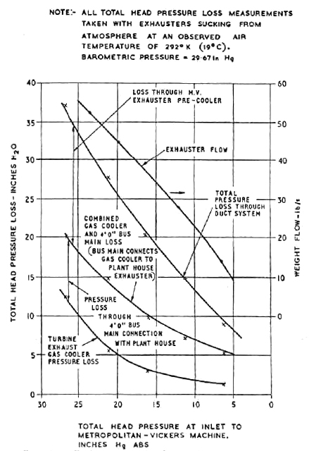
inlet manifolds in the Plant House. Exhaust gas coolers, each capable of
handling 60 lb/s at atmospheric pressure, are used to cool the gases before they enter the suction mains; maximum gas
temperature on the outlet side of the cooler is limited to 100°C. The installed pressure loss of the complete turbine
exhaust pipework operating under altitude conditions is shown in Figure 85, the losses for the turbine gas cooler,
the interconnecting bus-main to the Plant House, and
the Metropolitan-Vickers exhaust precooler are given separately; whilst the details of the
Battle House - Plant House
air pipework circuits are shown in Figure 6.
|
|
Fig. 85. Turbine test rig exhaust system pressure loss
|
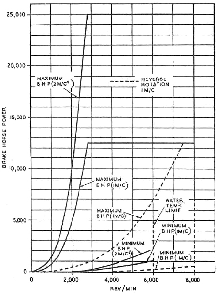
Two large Heenan and Forude hydraulic dynamometers are available to absorb the
power generated by the experimental turbine rig in the Battle House: they
are raged as follows :-
(a) 25,000 horse-power at 8,000 rev/min and
(b) 10,000 horse-power at 10,000 rev/min.
The larger of these two units is built in two independent sections and if low capacity
turbines are tested it is possible to obtain greater accuracy in power measurement at the lower end of the power
range if only one half of the complete 25,000 horse-power unit is used. This half unit aborbs 12,500 horse-power
at 8,000 rev/min.
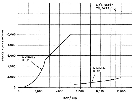
The characteristics of the two hydraulic dynamometers are given in Figures 86 and 87. However, in
addition to these two pieces of equipment, N.G.T.E. has twelve other smaller hydraulic dynaometers and a
range of eddy-current, solid friction and dynamometer motors that can be used for low powered turbine testing
work. This equipment is usually installed in smaller laboratories in the Plant House
and Old Site rig testing laboratories described in para. 28 and 29.
|
|
Fig. 86 Performance of Battle House turbines test hall 12500 to 25000 hp dynamometer
|
|
|
Fig. 87 Performance of Battle House turbine test hall 10000 hp dynamometer
|
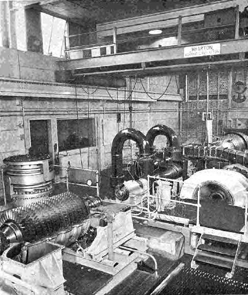
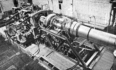
Figure 88 shows a Rolls-Royce Avon turbine and combustion system installed on the turbine test rig;
in this installation the experimental rig is coupled to only one half of the Heenan and Froude 25,000 horse-power
dynamometer.
|
|
Fig. 88. The turbine test hall with a Rolls-Royce Avon connected to one half of the Heenan and
Froude 25000 hp dynamometer.
|
The associated fuel system equipment is matched to the capacity of the experimental turbine
throughput and the maximum fuel flow is 1,600 gal/min at 1,000 lb/in2. The water cooling plant is sized to
absorb the full 25,000 horse-power of the large dynamometer.
A fully equipped control room has instruments to control and measure the experimental turbine
performance while a data aquisition unit produces punched tape for computer processing from the test data.
27. Naval Marine Wing
The Naval Marine Wing at N.G.T.E. has as its primary function the development and evaluation on engines
and their components for use in ships, and also detailed investigations into specific gas turbine problems having marine
associations. This work is conducted almost entirely on behalf of the Director General Ships, Ministry of Defence, but
the recent upsurge in development of hovercraft, in which many of the engine problems are similar to those encountered in
ships, together with the discovery by industrial operators in coastal sites that their operational environment is in
some respects 'marine', has somewhat widened the range of customers.
The naval test house, is capable of running several gas turbines and their associated machinery simultaneously
in test beds which have full performance instrumentation built into a central soundproofed control room. Dynamometer
cooling water supplies and cooling towers are available with a heat dissipation potential of up to approximately 33,000 hp,
and electrical load tanks for testing generators up to 1.25MW capactiy. A 10,000 or 25,000 horsepower dynamometer is
available to absorb power. Figures 89 and 90 show a general view of the Test House and Control Room.
|
|
Fig. 89. A general view of the Naval Test House
|
|
|
Fig. 90. The Naval Test House control room.
|
The organisation of the Wing is based on the ability to run engines continuously, so that endurance
evaluations can be carried out. Normal engine running achieves approximately 100 hours per week on any one engine,
but if required for a special trial, a 168 hour week can be worked.
The main problem of the marine environment is sea salf, either in the air or the fuel, and consequent corrosion
of the hot parts of the engine and a great deal of work is therefore devoted to means of removing this salt; in addition
field trials at sea are held to categorise the environment, and large-scale equipment for experiments with air filtration
has been built as well as separator units for removing seawater from fuel. Engine trials are also carried out with a view to improving
basic knowledge of the corrosion problem, and to evaluating the performance of different materials.
28. The Plant House New Site Rig Testing Facilities
There are two rig testing installations at N.G.T.E.; first on the New Site there are the
Plant House laboratories where altogether nine cubicles house different
research projects, secondly there are another group of laboratories on the original Old Site and these are described
separately in the next paragraph.
Normally in the Plant House the Metropolitan Vickers or
Parsons bleed air processing machinery outlined in para. 8 and 9 and shown pictorially in Figures 22 and 27 are used to supply
air to the test rigs, but as shown in Figure 6 it is possible to use the services of the G.E.C. compressors, para. 4, if
ever the Plant House equipment is out of action, by routing the
G.E.C. air through the 54in. main to Cells 1 and 2 and then through the
24in. mains to the Plant House. However, on account of the cost, it is a cardinal point
in the Establishment's testing policy that G.E.C. air will not be used in the Plant House rigs
if compressed air is available from the less expensive Metropolitan-Vickers 6:1 plant and in any case specific safety precautions
must be observed to prevent accidental damage and danger to personnel when G.E.C. air is used in the Plant House
cubicles.
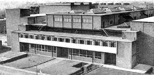
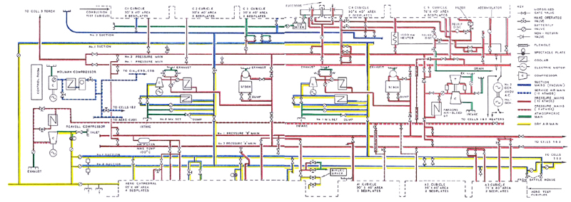
Figure 91 shows a general view of the Plant House building;
the central part of the building houses the compressor machinery while the rig laboratories are sited on either side. The
location of the test rigs relative to the air processing plant and the arrangemetn of the different air pipework circuits
are shown in detail in Figure 92. Rig cubicles on one side of the Plant House building
concentrate on aerodynamic rig resting, whilst those on the other deal with combustion tests. Two 24in. diameter bus mains supply
compressed air to the test cubicles from the Metropolitan-Vickers 6:1 compressors and the Parsons 4:1 air bleed gas turbine which
are described in para. 8 and 9; running programmes are planned so that both compressed air services are not required together.
|
|
Fig. 91. External view of Plant House building
|
|
|
Fig. 92. Diagram of Plant House air main and rig connections.
|
A separate 15in. diameter pressure main routes air from the Reavell 2½:1 compressor to
aerodynamic cubicles No. 1 and 2 but provision exists for this pipework to be extended to the other aerodynamic cubicles if
required. Suction services from the Metropolitan-Vickers machiens are supplied to the test cubicles for altitude experiments
through two 48in. diameter vacuum mains. Figure 92 shows how the bus mains are installed on both flanks of the central compressor
hall so that the compressor/exhausters can serve the aerodynamic and combustion laboratories using cross-over mains
when necessary to give flexible operation.
The twin 48in. diameter suction mains are connected at the west end of the Plant House
building to the delivery pipeline from the Ceca air drying plant, Section 2, para. 11,
so that both the Metropolitan-Vickers and Reavell compressors are able to supply dry air to the test cubicles when this service
is required. In fact, as shown in Figure 6, the Plant House suction mains also
form an integral part of the circuit for routing the dry air service to Cells 1 and 2
when the ejectors suck dry air at atmospheric pressure through the engines tested in these cells.
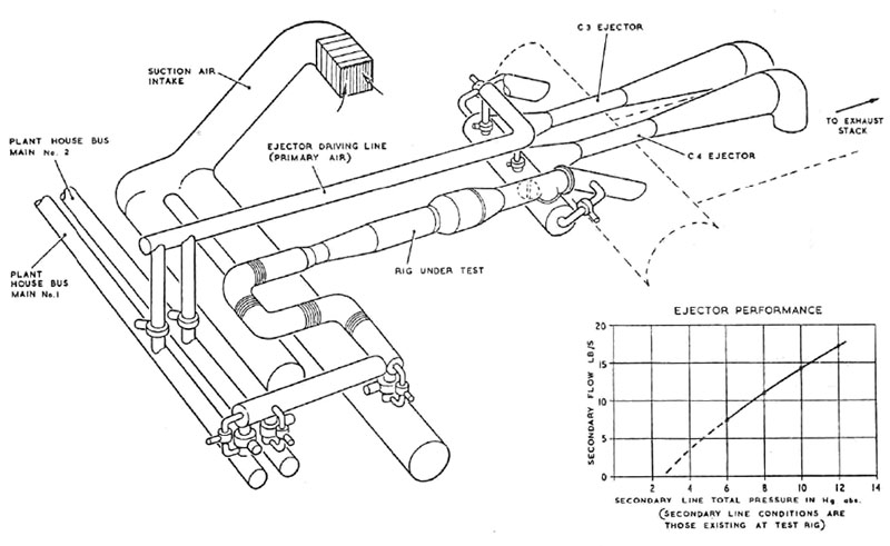
In the original Plant House design layout, it was intended that
the Metropolitan-Vickers 6:1 exahuster plant should create altitude conditions in the combustion as well as the aerodynamic
test cubicles and special exhaust gas coolers were provided with this purpose in view. However, experience of the operational
risks with fully carbueretted air streams in which all the fuel has not be completely burnt caused a change in policy
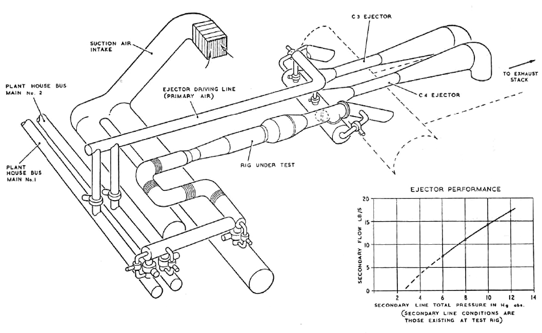
and consequently an ejector plant has been installed to exhaust combustion rigs of altitude tests. These ejectors are matched
to the Metropolitan-Vickers 6:1 air supply and can swallow a test rig flow of 17lb/s at 12in Hg abs. calling to 7.5lb/s at
6in Hg abs. The arrangement and output of this ejector plant is shown in Figure 93.
|
|
Fig. 93. Diagrammatic layout of Plant House ejector plant
|
In certain rig tests, particularly those on combustion components, hot air is required
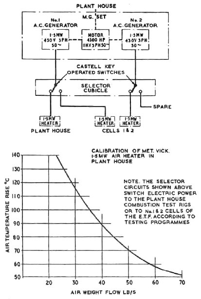
and for this purpose a 1.5 MW heater is installed as part of the Plant House
equipment. This unit has approximately half the output of the electric heater fitted in
Cells 1 and 2, and referred to in para. 13; the actual
performance is shown in Figure 94. The electricity for this 1.5MW heater is produced by the same generator
that feeds the Cells 1 and 2 electric heater and special switches
monitor the current either to the Plant House or to
Cells 1 and 2 installation; in consequence tests using the
3MW heater in Cells 1 and 2 must be programmed to avoid
interference with Plant House requirements and vice versa.
|
|
Fig. 94. Electrical switchgear diagram and performance of Plant House 1.5MW heater.
|
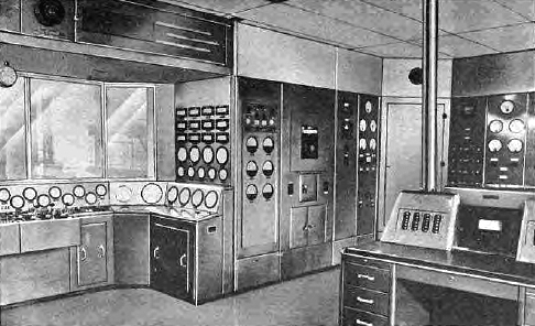
Figure 95 shows one of the combustion cubicles and illustrates how each cubicle
houses two or three rigs apiece. Each test cubicle has at least two bed plates, and in fact, two
test beds have four each, these details and sizes of cubicles are listed in Figure 92.
|
|
Fig. 95. A typical Plant House test cubicle.
|
Separate control panels are arranged for each experiment to suit particular requirements;
frequently, when safe to do so, personnel will conduct their tests from stations next to the test rig.
The cooling water and fuel supply plant serving the Plant House
laboratories are described in para. 41, 42 and 43.
29. Old Site Rig Testing Facilities
Before the extensive New Site installations including the Engine Test Facility were built, rig testing
was restricted to a small gorup of laboratories in the older part of the Establishment. These facilities are still in
service and contribute directly to the Establishment's research programme. They are self-contained except for the incoming
electricity supply which is routed via the New Site electrical sub-station in the manner described in para. 38.
The available air machinery is restricted to compressing duty except for two Holland exhausters;
this equipment has already been described in para. 10.
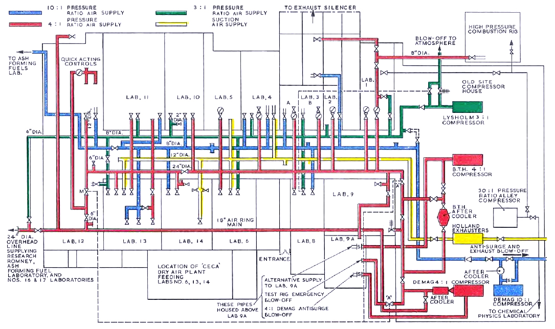
The Old Site comprises 17 test laboratories all of which house experimental test rigs or wind tunnels
broadly similar to those installed in the Plant House building, except that their
capacity, both in throughput and operating pressure is usually less because of the restrictions introduced by air
machinery limitations.
The general arrangement of laboratories and the different bus connections are shown in Figure 96.
These are four main pipeline circuits, two of which are 8in diameter, carrying the Lysholm 3:1 and Demag 10:1 pressure
ratio supplies; the third, a 12in main connects the small Holland exhauster machines to the rigs; the fourth, a bus main
of 24in diameter is used to supply the output from the 4:1 B.T.H. and 4:1 Demag compressors to the different rigs. THese
bus mains are not coonected to each of the laboratories in every case although in particular instances there are more than one connection
to a laboratory; recently, a 2in diameter circuit to supply high pressure at 30:1 pressure ratio has been installed;
the detials of the actual Old Site laboratory air circuits are given in Figure 96.

|
|
Fig. 96. Arrangemen of air supply plant and test laboratories N.G.T.E. Old Site.
|
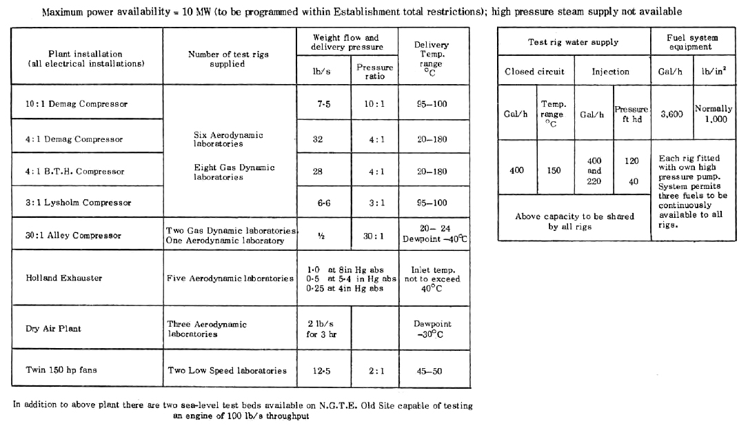
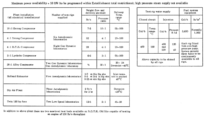
Table XIII summarizes the plant available on the Old Site for rig testing. For completeness, the table
includes small flow Alley high pressure ratio compressor for high pressure combustion tests, the minor low speed plant
which is fitted with two low pressure ratio fans but which are useful for low pressure ratio research projects which do
not need high capacity facilities and the two sea-level static test beds than can handle engines of 100 lb/s capacity.
Table XIII
SUMMARY OF OLD SITE PLANT FOR RIG TESTING
© Procurement Executive, Ministry Of Defence
|