 | Data Gathering In The Engine Test Facilities |
4.1 Introduction
The data gathering facilities provide a comprehensive, flexible and accurate measurement
capability. A wide variety of instruments measure engine parameters to provide a direct display of various
test data in each cell control room and to generate information for the data gathering system.
Plant behaviour is also monitored in a similar manner, instrumentation being used to gather,
present and record information and to provide signals for closed loop control.
Digital, analogue and hybrid electronic circuit techniques in conjunction with transducers act
to convert and process information from physical processes into electronic analogues. Each test cell is equipped
with two data gathering systems, known as the steady state data gathering system and the transient data gathering
system.
The steady state data gathering system is used to measure and tansmit test data from each test
cell to a central computer. This system is used primarily for precise calculation of engine test performance
figures at various steady state conditions. The transient data gathering system is used to record data generated
by engine transient performance tests, the recording medium being either light sensitive paper or magnetic
tape. In addition, there is a digital computer based transient recording system.
The nature of electronic equipment, coupled with rapid advancements in technology,
require the instrumentation systems to be constantly reviewed and updated to keep pace with developments
and so offer the most effective and accurate engine performance assessment. Special systems may be
installed to meet specific customer requirements where the existing systems are not suitable.
Paragraphs 4.2 to 4.6 provide details of the data gathering systems installed in two
of the test cells at N.G.T.E. Essentially similar facilities are or can be
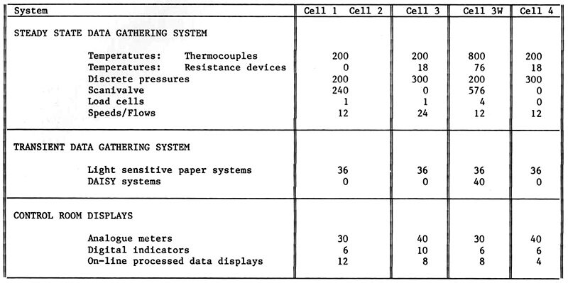
made available in the other test cells. Table 4.1 provides a summary of the main features of the
instrumentation channels in all the test cells. Paragraphs 4.7 to 4.10 deal with the support services
which are available to the engine test facility.
Table 4.1
Summary of instrumentation channels available to E.T.F. cells
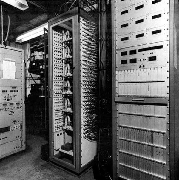
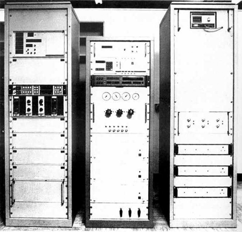
4.2 Cell 3 West Steady State Data Gathering System
The layout of equipment used in the steady state data aquisition system is shown
pictorially in Figure 4.1.
|
|
Fig. 4.1 Computer installations for steady state data acquisition
|
4.2.1 General Description
Seven hundred pressure channels and eight hundred temperature channels are available
together with a load cell based thrust measurement capability. A range of conditioning electronics is also
provided to meet the needs of a variety of differing signal sources. The central computer data handling
capacity is 1000 channels, but the number of hardware channels available to the
Cell 3 West data gathering system permits a larger
quantity of instrumentation to be connected for an engine test series, so that the choice of channels
for a specific engine test can be made by relatively minor changes to the data gathering program rather
than by time consuming and error prone piping or instrumentation alterations.
Gas pressures are measured by 200 discrete transducers or by a 500 channel pneumatic
pressure scanner; up to 10% of the discrete transducer channels may be used for wet pressure measurement.
The acquisition rate for the scanner averages 38 pressures per second and for the discrete channels this
rate is increased by a factor of more than two.
The temperature measurement systems provide mainly for chromel-alumel thermocouples
and are equipped with ice flask cold junctions, but extneral systems utilising thermal planes can also
be accommodated. Twentry four channels are allocated to 100 ohm resistance-temperature devices. Scanning
is at a low signal level and is implemented by means of reed relays followed by logic switching onto the
data highway. Reed relay settling times are 11 milliseconds for the 200 channel system and 1.6
milliseconds for the 600 channel system.
Twenty channels are available for multiplexing Binary Coded Decimal (BCD) data ont othe
central computer interface, ten of these channels may be sub-multiplexed so that each will accept 100
instruments.
4.2.2 Pressure Measurement
(a) The discrete transducer system
The transducer used in this system is the SE150 variable reluctance type, for
which the manufacturer quotes a non-linearity of 0.25% fullscale. By selection and temperature control
of the transducer cabinets, errors from a fitted straight line can be reduced to better than 0.1%
fullscale. The transducer used for wet pressures is the SE1150, which is a derivative of type SE150
with the added advantage that the fluid is not in contact with any material other than stainless steel.
The transducers are piped to spool valves which enable the transducers to be connected to an
engine test pressure or, by selection, to a calibration manifold. The spool valves are selected to the
CALIBRATE positions pneumatically by remotely switched solenoid valves. Multipoint calibrations are
implemented daily on-line to the central computer and the calibrations restored for use during engine
testing.
Signal multiplexing is implemented at low level by reed relays which select a discrete
transducer for signal conditioning. Analogue to digital (A-D) conversion is followed by logic multiplexing
of the BCD data onto the computer highway.
(b) The pneumatic pressure scanner
The pressure scanner is a proprietary 12-valve "Scanivalve"
as shown in Figure 4.2. Each valve provides a means for connecting sequentially
each of 48 input ports to a shared "Druck" PDCR 22 pressure transducer. The total
number of ports available is 576 of which 62 are dedicated to reference pressures,
the remaining 514 are available for engine or plant test pressures.
|
|
Fig. 4.2 Cell 3 pneumatic pressure scanner
|
The flush diaphragm PDCR 22 is an integrated silicon strain
gauge transducer which is manufactured specifically for use in the "Scanivalve".
Its low volumne, negligible hysteresis and non-linearity of better than 0.06%
full-scale, make this transducer particularly well suited for pressure scanner use.
Signal conditioning is provided by twelve "Druck" DPI 100 units provide the
polarising supply for the transducers and include signal linearising to better than
0.04% full-scale. A-D conversion is also achieved within the DPI 100 which provides
a local display and a 4.5-bit BCD output which is then logic multiplexed onto the data
highway.
Address selection is by a 19-bit address word which steps the scanner to the
required port, allows a 150 millisecond pneumatic settling time and then commands A-D
conversion of the transducer signals. Logic multiplexing allows the data from each valve
to be selected rapidly onto the data highway in turn. A complete scan of the 576 ports takes
approximately 15 seconds.
Because of the inherent linearity of the silicon strain gauges
it is not necessary to implement multipoint calibrations. Reference pressures
are applied to dedicated ports from either quartz-Bourdon tube instruments or
a self-regulating dead weight tester which allows two point calibrations, atmospheric
plus one reference pressure, to be implemented on each rotation of the scanner.
This minimises errors due to zero and span drift. Data and calibration are collected
at the same time and the reference pressure can be selected to be close to test data
values if required. Absence of hysteresis means that interporting is not required
and the errors due to ttravelling volume are less than 0.05% full scale. Calibrations
are traceable to National Physical Laboratory (N.P.L.) standards, the chain of
traceability being explained in paragraph 4.7.
4.2.3 Temperature measurement
(a) Thermocouple channels
The 800 thermocouple channels from the test cell and plant are changed from chromel-alumel to
copper lines in ice flask cold junctions and fed into the data room via 800 twisted pairs. The 19-bit address word
from the computer is decoded to select a discrete thermocouple output for amplification. After the appropiate delay
to allow relays and amplifier to settle, A-D conversion is commanded and the 4-bit BCD output is logic multiplexed
onto the data highway.
On-line confidence checks are provided by a d.c. voltage source which allows reference voltages
of 0.025% full-scale to be applied via dedicated addresses to amplifiers and A-D converters. Temperature data is
compared with a standard calibration stored in the computer unless specific thermocouple calibrations are available.
System resolution is 0.125°C.
(b) Resistance temperature devices
Signal conditioning is provided for twnety-four 100 ohm resistance temperature devices. The conditioning
modules are proprietary Rosemount units which provide linear current and voltage output proportional to temperatures in
the range -50°C to 500°C. Signal voltages are attenuated and applied to the temperature system A-D converter
via reed relays; multiplexing is as for the thermocouple signals.
4.2.4 Binary Coded Decimal (BCD) Data
BCD data may be accepted from miscellaneous instruments provided that the necessary "handshake" can be
achieved with the central computer. Data word length is limited to 4.5 bit BCD. Logic multiplexing is used throughout
and facilities exist for addressing an external sub-multiplexer if this is required. Up to 100 instruments can be sub-multiplexed
onto a single BCD data channel and 10 such channels are provided. A further 10 channels are available which are not
expandable.
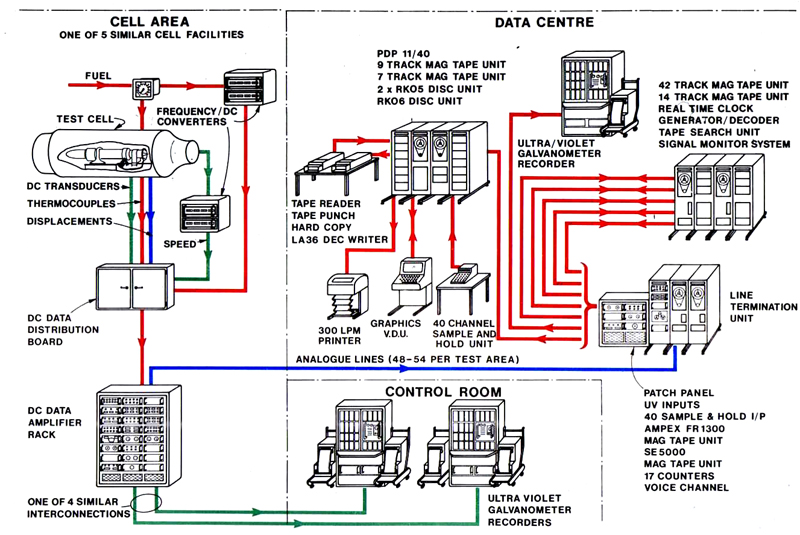
4.3 The Cell 3 West Transient Recording System
The layout of equipment used in the transient recording system is shown pictorially in
Figure 4.3.
|
|
Fig. 4.3 Data acquistion systems for transient performance measurement
|
4.3.1 The Analogue Transient Recording System
The Cell 3 West analogue transient recording system
comprises a set of data amplifiers, a set of galvanometer drive amplifiers, a set of transducers and two ultra-violet
light operated direct writing oscillographs type SE 3012 (manufactured by S.E. Laboratories) commonly referred to
as UV recorders. A third UV recorder is available if required.
Twenty channels are available on each recorder and the paper operating speed may be selected from
the standard ranges 1.25, 2.5, 5, 10 and 20 m/s. This speed may be multiplied by a factor of 10 or 100 and
each recorder can be operated independently or as part of a common master/slave node with synchronised chart drives.
The paper width is 12 inches and grid and timing lines can be automatically printed on the chart together with
channel identification.
Forty-eight data amplifiers type DA255A manufactured by Fylde Limited are used in
Cell 3 West to generate signals for the galvanomenter drive amplifiers
type "Dana" 2720.
Galvanometers are available with different sensitivites, frequency response and damping requirements.
The amplifier system in use can be closely matched to the driving needs of most galvanometers and a specification of
a fequency response "flat" from virtually d.c. to 1KHz can be provided if required.
The "Fylde" DA255A is a compact high frequency low drift low noise differential d.c. amplifier
fitted with an integral power supply. It is equipped with a variable gain control which is adjustable from x5 to
x2000 and can thus be used to provide conditioning for transducers with a wide range of sensitivities.
4.3.2 The Digital Transient Recording System
The digital transient data gathering system at N.G.T.E. was introduced to
satisfy two main objectives:
- the need for greater precision in the measurement of engine related transients.
- the need to minimise the quantity of UV paper rolls produced during each test and thus to reduce the amount of
work and time necessary to extract useful data from each roll.
The first objective has been satisfied by a combination of digital techniques together with, in the case of pressures,
a transducer/water jacket combination designed to extend the effective measurement bandwidth. The second objective has
been met by using a digital computer as the main data processing device. The computer, together with its attendant
peripherals, provides a more compact and relevant presentation of results than is possible with UV paper. The computer
program which operates the digital transient data gathering system is known as DAISY (Digitising Analysis Information
System) though the toal hardware/software package has become known as the DAISY system.
The DAISY system hardware consists of a set of transducers and associated analogue electronic
conditioning modules located in and near the test cell, together with a set of further conditioning amplifiers,
filters and sample and hold units - one of each per input channel - located in the Data Centre
(see para 4.9). An input multiplexer, analogue to digital converter and PDP 11/40 computer complete the main
items of the installation.
The PDP 11/40 computer is equipped with 44K words of available direct access memory
(16-bits), two RK05 plus one RK06 disc cartridge drives with a storage capacity of 1.2 megabytes
and 7 megabytes respectively all of which are available for direct access storage, though the
operating system plus other files use part of one cartridge. The other peripherals available
include a console typewriter, a line printer, two digital magnetic tape drives and a Tektronix 4010
Visual Display Unit with a hard copy unit. An SE 5000 42-track analogue tape recorder is also
available for back-up storage.
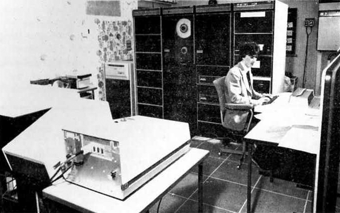
|
|
Fig. 4.4 DAISY computer and peripherals
|
The Data Centre (see para 4.9) also
houses the computer input-output sub-system for interfacing the analogue signals made
available via land lines from the test cell area to the PDP 11/40 computer. This system was
manufactured by Micro Consultants Limited and comprises a set of modules from their standard
Modular 15 range. A 40-channel A-D converter digitising at a resolution of 12 bits and a
maximum throughput of 38kHz, amplifiers, active filters and parallel sample and hold
on each input are included in the modular package. Also included are a number of D-A converters
and a DEC PDP 11/40 Input/Output bus interface module.
Signals for the DAISY system originate from engine mounted transducers
and are generally a mixture of speeds, flows, pressures and temperatures. The pressure
transducer used for this system is the PDCR 22, manufactured by Druck Ltd, in conjunction with
hypodermic tubing and a water jacket designed by N.G.T.E. to provide maximum
environmental protection to the transducer whilst at the same time reducing the pneumatic volume
associated with the sensing input to the least possible value.
4.4 Cell 3 Steady State Data Gathering System
The Cell 3 data gathering system
is equipped with approximately 700 input channels and performs four basic functions:-
- accepts instructions from a computer-interface.
- decodes the instructions into addressing and function commands and implements such commands.
- converts the subsequent analogue signals into digital format.
- makes the digital data available to the computer interface.
All the hardware is housed in five enclosed 19 inch standard instrument racks
which also accommodate the control panel for the local manual control facility. Pressure measurements
are implemented by means of SE150 pressure transducers, three hundred of which are provided and
arranged in the form of 30 modules, each module housing 10 transducers. A module consists of a
temperature controlled enclosure for the transducers, multiplexing reed relays, demodulator,
control logic and change-over solenoid valves which permit each transducer measurement port
to be connected to either a measured calibration manifold or the unknown pressure being measured.
A multipoint calibration of each pressure transducer is implemented daily
using quartz-Bourdon tube pressure sources as the working standards, the central computer being
used to gather and process the resulting data. All the working standards are traceable to National
Standards at the N.P.L.
The temperature measurement is implemented mainly by chromel-alumel
thermocouples, cold junction compensation being provided by ice flask reference junctions.
Signal conditioning and multiplexing is provided for 200 thermocouple signals.
The change from chromel-alumel to copper wire is made in ice flask reference junctions which are
located near the test cell. The temperature system amplifier and reed relays are located within
the Data Room control cabinet and share the address
decoding and A-D with the pressure measurement system.
Provision is made for averaging up to 20 thermocouple signals using operational
amplifiers and the average value is routed to the computer as a standard thermocouple signal.
Signal conditioning is also provided for eighteen 100 ohm resistance temperature
devices and six 130 ohm instruments. Temperatures in the measured range -50°C to 500°C
may be measured by proprietary Rosemount units. Signal voltages are multiplexed onto the signal
A-D converters via reed relays.
Low level reed relay multiplexing is used to connect both pressure and temperature
systems to a common A-D converter. The data aquisition rate for the installation is approximately 80
channels per second.
As with the Cell 3 West system and in
common with the other test cells, on-line confidence checks are provided by a d.c. voltage source
which allows reference voltages of 0.025% full-scale accuracy to be applied via dedicated addresses
to the temperature and pressure channel amplifiers and to the system A-D converters. Temperature system
resolution is 0.125°C.
The installation also measures engine thrust, as thrust is converted into a proportional
hydraulic pressure by means of a Macklow-Smith hydraulic capsule. See also para 4.6.
System control is exercised by an 18-bit word, and 27-bits are used on the data output
section of the system, corresponding to six BCD decades.
4.5 The Cell 3 Analogue Transient Recording System
The Cell 3 transient recording system
is similar in concept to that already described for Cell 3 West
in para 4.3.1 and therefore consists of similar main sections i.e. a set of data amplifiers, a
set of galvanometer drive amplifiers, a set of transducers, and two ultra-violet light-operated
recorders. The specification for the recorders in Cell 3
is identical to that for the recorders in Cell 3 West.
The galvanometer driver amplifiers and data amplifiers are however different and were manufactured to
N.G.T.E. specification and design though they perform broadly similar tasks to
the units in Cell 3 West.
Data amplification (for low level signals) in the cell Data Room is accomplished using
the N.G.T.E. data amplifier. This consists of to separate channels, one for amplifying
d.c. signals and the other for amplifying a.c. signals. By this means, the low drift chopper amplifer
used for d.c. amplification does not restrict the frequency response since signals over 7Hz are
handled by the a.c. channel. The signal from the d.c. channel is then added to the output of the a.c.
channel by the summing and power amplifier. Gain is controlled by a potentiometric feedback system
and the complete unit has the desirable attributes of low noise level, low drift, high input
impedance and low output impedance over a wide bandwidth. The switchable gain ranges are
10, 20, 50, 100, 200, 500 and 1000.
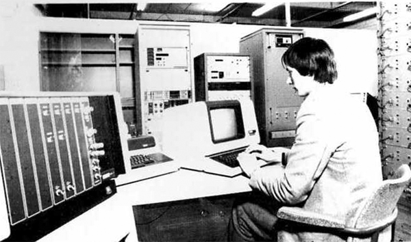
|
|
Fig. 4.5 Data aquisition in Cell 3
|
The N.G.T.E. galvanometer drive unit has adjustable
gain and variable bandwidth controls and produces acurrent output to drive a galvanometer.
Each unit consists of a differential d.c. amplifier and a galvanometer drive converter
and a relay switching facility is provided so that the input to the galvanometer drive
amplifier can be disconnected and a calibrating input substituted. A manually
adjusted backing-off voltage can also be introduced into the virtual earth point of the
operational feedback configuration. The switched gain ranges are 1, 1.5, 2, 3, 5, 7
and 10 and the bandwidth may be limited to 10, 30, 100 or 300Hz if desired.
A total of 20 channels can be recorded on each UV recorder, but in
practice less than this number is used to avoid the problem of trace congestion on the
paper.
4.6 Engine Thrust Measurement
The measurement of thrust generated by the testing of gas turbine
engines in N.G.T.E. test cells is implemented in a number of ways,
though all utilise some form of load cell as the sensing element. The engine in
Cell 3 West hangs from a test frame inside
the cell, the whole assembly being free to move a finite distanc in either direciton along the
axis of the cell. Four load cells are fixed rigidly to the cell structure and restrict
the travel of the two thrust legs which form part of the test frame. Each load cell comprises
a stressed high tensile steel element fitted with bonded foil strain gauges, trimming and
temperature compension resistors being included in the bridge network. The chamber immediately
surrounding the guaged area is oil filled for temperature equalisation and the hermetically
sealed steel case is water jacketed to provide a stable thermal environment over all running
conditions. The internal temperature of the load cell is monitored by means of two
thermocouples. Each load cell is permanently bolted into position in the test cell and
calibrations are effected using other transfer standard quality load cells.
The voltage outputs from the transfer standards are measured on a high
precision digital voltmeter which also make available a BCD output for multiplexing onto
the data highway of the main data gathering system. The transfer standards are taken periodically
to the National Standard kept at N.P.L. and updated calibrations obtained.
|
|
Fig. 4.6 Computer controlled pressure standard in Cell 3
|
The strain guage bridges which form part of each type of load cell are
energised by regulated power supplies, each load cell having its own supply. A precision
digital voltmeter is available to monitor energisation at the bridge terminals via separate
monitor lines. A further set of lines is used to sense the bridge potential difference across
the strain gauges bridges and to control the power supply by means of suitable feedback
to always maintain energisation at the desired value, irrespective of small load changes
for example. A signal voltage arising from a bridge unbalance caused by a force being
applied to a load cell is amplified by a data amplifier and the resulting analogue made
available to an address on the steady state data gathering system. The required address at
any given instant is selected and sampled by the computer as instructed by the computer
program.
Thrust generated by eninges under test in Cell 3
is measured by an extension of the main steady state pressure system. The engine test bed is
suspended from four pillars located at the corners of the test frame and oil is pumped into bushes
in the pillars to float the bed which is then free to move under engine thrust. Movement is
restricted by thrust and monitor capsules which are maintained in contact with the bed
by means of a nitrogen pre-load system. Thrust, acting on the 20in2 capsule
diaphragm is transmitted via a silicon filled capillary tube to an SE 1150 transducer,
with an effective 20:1 reduction. Energisation and signal conditioning for the water cooled
transducer is again provided within the common system. Calibration is achieved by interposing a
proving ring between the test bed and a hydraulic jack, the proving ring being preiodically
checked at the N.P.L.
Note: The thrust measurement systems described in para 4.6 will be changed in 1982
to improved arrangements, utilizing Bofors shear force load cells.
4.7 Calibrations and Calibration Standards
4.7.1 Introduction
The purpose of instrumentation is to measure and present parameter
values. However, this measurement and presentation process can never be achieved
with absolute accuracy and certainty, there always being doubt, however small,
that the presented value exactly equals the true value of the parameter.
The magnitude of an error is ascertained by comparing or
calibrating the system against another system of previously established accuracy.
The results obtained from the calibration process are influeneced
by two main factors. First, in order not to degrade the potential accuracy of
the system under test, the calibrating standard used at N.G.T.E.
exhibit accuracies several times better than that of the system being assessed. Secondly,
the chain of calibration used at N.G.T.E. leads directly or
indirectly to the National Standard at the N.P.L. or to the American National
Bureau of Standards (N.B.S.). The interim calibrations between the
N.G.T.E. and National Laboratories are monitored and assessed
by independent organisations to ensure that the calibration quality is maintained.
By maintaining calibration standards, procedures and documentation
it is possible to assess the magnitude of any inherent error in a measurement system
and to identify its significance, if any, to the resultant data obtained. In
this way it is possible to identify the sources of any inbuilt errs in the measurement
and calibration systems, thus permitting further imrpovement to be made to the quality
of the data obtainable at N.G.T.E.
Pressure, voltage, load and flow parameters reqire frequent
measurement at N.G.T.E. and as examples
of calibration procedure the traceability to N.P.L. of each of these measurements
are briefly explained.
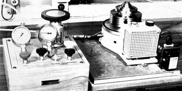
4.7.2 Pressure calibration
Daily calibration of the steady state pressure transducers and less
frequent calibration of the transient pressure transducers and their respective
measurement systems are achieved using quartz-Bourdon pressure test sets. These
pressure test sets are periodically calibrated against a dead weight tester model
2465-751 which is the N.G.T.E. transfer standard. The transfer
standard is regularly sent to the Sira Calibration and Standards Centre which
is itself periodically compared with the National Standards at N.P.L. Calibration
of the transfer standard is carried out using procedures and in an enviroment
approved by the British Calibration Service (B.C.S.).
|
|
Fig. 4.7 N.G.T.E. primary pressure standard
|
4.7.3 Voltage (d.c.) calibration
The direct input d.c. voltage channels on the data gathering systems are
calibrated usign working standards known as millivolt sources. These sources are
also used to calibrated test instruments such as the many voltmeters, etc., in daily use throughout
the Establishment. The millivolt sources are checked periodically by the electronics workshop
staff using the Establishment's transfer standards, which are Datron type 1051 and type 1061 multi-purpose
digital voltmeters. The transfer standards are regularly returned to the manufacturer or to
the E.M.I. Measurement standards Laboratory for comparison with other devices directly
traceable to N.P.L. The Datron instruments also provide traceable calibrations for a.c.
voltage measurement and for resistance measurement at N.G.T.E.. Calibration
of the transfer standards are again implemented using procedures and in an enviroment approved
by the B.C.S.
4.7.4 Load cell calibration facility
Load cells, such as those used in the engine thrust measuring systems,
may be calibrated at N.G.T.E. using a dead weight testing rig. The
dead weight tester is a device for applying load to load cells (force transducers) uder
well defined conditions.
It consists of a set of steel masses which are raised in turn by lifting
a central rod. The rod is attached to one or two load cells (at present tension and shear force
are catered for)and as each mss or pair of masses is lifted, a repeatable (0.01% or better)
increment of load is added to the cell under test.
The system is reaised by means of a hydraulic ram and lever. The ram is
energised by a hand pump under the control of the test operator. Readings are taken only
when the required masses are lifted free of any obstruction and when the remaing masses
are not touching those lifted. Under these conditions the only force on the load cell should be
gravity, which is very repeatable.
Any friction would introduce errors. There are two tests for friction.
One is to observe the decay of any oscillations of force on the load cell output; the
other is to apply a small incremental weight (about 1kg) and remove it - a corrseponding
increment of output should be observed only when the extra weight is applied.
The tester can be used for incremental loading, decremental loading
(i.e. unloading), for creep tests, and for investigation of the effects of both
uniform temperature and temperature gradient on ouput.
Because the masses have not been closely adjusted, the tester is NOT
a Primary Standard. Its increments are apprximately 0.5 ton-force but are not exactly
equal. It is calibrated as a Secondary Standard against the N.P.L. Primary Standard by using
load cells (two or more) as transfer standards. Once calibrated, and in the absence of
damage or disturbance, it is expected to maintain its calibration indefinitely.
Summary of performance
10 increments of load each of apprximately 0.5 ton.
Increment arbitrary but stable to 0.01%.
Incremental and decremental loading.
Creep testing.
Evaluation of temperature effects.
Accommodates tension and shear-force load cells up to
10 tons rating, but tests only to 5 tons.
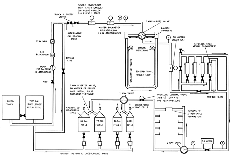
4.7.5 Fuel Flowmeter Calibration Facility
During a test run on a gas turbine engine the fuel flow rate may
vary over a range of 10:1 and the accuracy of measurement required for
performance assessment must be within 0.15 per cent throughout this range.
The fuel flowmeter calibration rig is employed to calibrate the meters which
make these measurements. It can provide calibration over a range of flows
from 1.9 gallons/minute (0.14 litres/second) to 250 gallons/minute (19 litres/second)
with a specified accuracy of 0.05 per cent of reading.
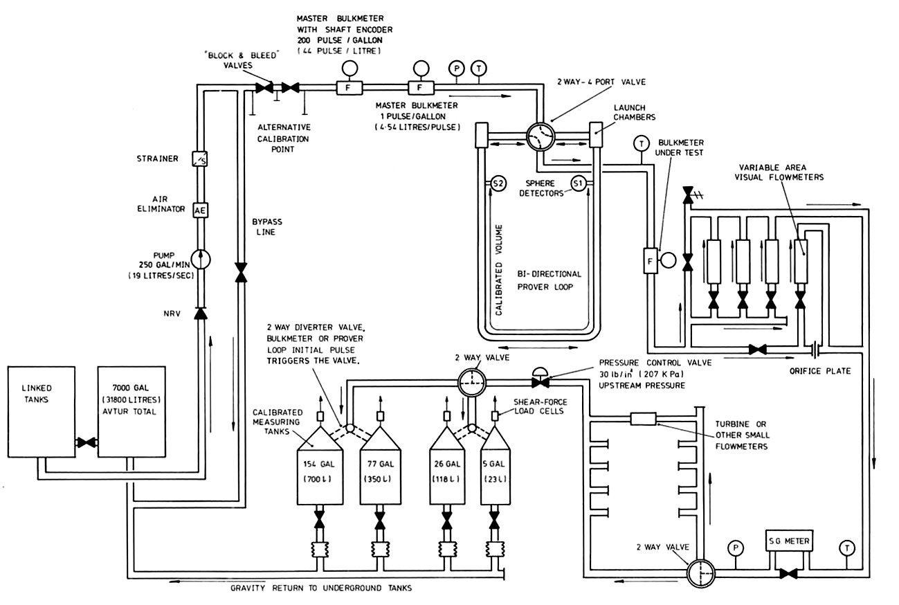
Figure 4.8 is a schematic layout of the rig. Positive
displacement or turbine type flowmeters may be calibrated and are piped in
series with the following measuring equipment : -
- two positive displacement flowmeters
- a pipe prover
- a bank of variable area flowmeters (used for setting up and monitoring purposes)
- a specific gravity meter
- a group of four weighing tanks
|
|
Fig. 4.8 Diagramatic arrangement of the Fuel Flowmeter Calibration Facility
|
This equipment is housed in a measuring room and is supplied with
Avtur fuel pumped through a strainer and deaerator from two underground tanks,
external to the building. After passing through the measuring system the fuel is returned to
the storage tanks. Each measuring unit can be by-passed and a separate line is
provided to by-pass the complete measuring assembly. The arrangement of the units in series
allows cross calibration between various reference units. A pressure control valve maintains
the pressure in the circuit upstream of the weighing tanks above 30lb/in2.
The rig is controlled from a panel housed in a control room adjacent
to the measuring room. All electrically sensed data is fed to the panel for display or
processing by computer. The variable area meters may be viewed through a window in
the partition between the two rooms.
All electrical equipment in the measuring room is installed to flameproof
or intrinsically safe standards and metalwork is bonded to earth. Control lines
to electrical equipment in the rig are protected by Zener barriers. Hydrocarbon detectors
give warning of dangerous concentrations of fuel vapour.
Four methods of calibration are available:
- Pipe power
- Volume 77.3 gallons (351 litres); working range 15 gallons/min (1.14 litres/second)
to 251 gallons/minute (19 litres/second).
- Two master meters
- Positive displacement with digital encoder 200 pulses/gallon (44 pulses/litre) maximum
flow rate 250 gallons/minute (19 litres/second)
- Positive displacement with one pluse/gallon (4.54 litres/pulse). Maxiumum flow rate
250 gallons/minutes (19 litres/second).
- Four volumetric measuring tanks
- Tank volumes 5 gallons (23 litres), 26 gallons (118 litres), 77 gallons (350 litres),
154 gallons (700 litres)
- Direct weighing of the four tanks in '3'
- Each tank is suspended from a shear force load cell.
The calibration factor of a meter (e.g. the volume passed for one pulse
registered) is obtained by dividing the measured volume (of the volume calculated from the
measured mass) by the number of pulses. Flow rate is determined by dividing volume by
measured time.
Each calibrating unit has been checked against local
standards either at N.G.T.E. or by the manufacturer. Hence the calibration
can be traced by to National Standards. In addition the calibration units can be
cross checked against each other.
4.8 Closed Circuit Television
Closed circuit television is used for a number of monitoring functions in
the test cells. The cameras are adjustable to view the desired part of the installation such as the surveillance of
engine nozzle, jet pipe, engine oil level, air and oil vents, fuel and oil leak detection,
helicopter intake icing and reheat flame colour observation. The camera control panels are
located in the control rooms together with the monitor associated with each chain. One
of the important applications is to observe the formation of ice on engine intakes or
first stage engine compressor blades. The problem of observing a set of blades
during actual engine running is overcome by means of a stroboscopic light source
which is synchronised to engine speed and the control of the light allows each individual
blade of a rotating compressor stage to be examined individually. Another important application
is the viewing of fully reheated engine exhausts using complex cooled optical periscopes
located in the centre of the after-burner exhaust.
The camera heads ued for general observations in the test cells are of the
solid state "Sentinel" type and are protected by substantial water-cooled/heated
housings which also incorporate heated windows. A choice of lenses is available covering
a range of focal lengths and apertures.
N.G.T.E. also provides video recording facilities for
events which occur in the test cells. Six IVC 800 series helicalscan recorders are available
which can operate on 50 field/625 line monochrome or PAL colour standards. N.G.T.E.
has a maximum recording capacity of four colour channels and two monchrome at an time.
The tape used is one inch wide and privdes up to one hour of full recording from an
eight inch reel (2150 feet) of tape. Full 5MHz bandwidth broadcast standard video-recording
is provided by this equipment and in addition two audio channels are available on each
machine. Stop motion and slow motion capability is also provided and basic editing
functions can also be implemented.
Colour TV chains at N.G.T.E. are based on equipment
supplied by Shibaden Ltd. The camera head is of the three gun type and is fitted with chalnicon
tube and also contains the camera coil drives, wave form generator and video pre-amplifier
circuits. The camera control unit contains the synchronisation pulse generator, PAL
encoder board and colour bar generator. The monitor is an 18 inch studio colour monitor
with Red, Green, Blue and PAL inputs.
To make the identification of recorded events easier, Video Number Generators
are available which superimpose both time and event numbering information on the scene being
viewed. The first three characters represent the event number in the range 000 to 999
and the remaining eight characters show hours, minutes, seconds, tenths and hundreds of
a second. The generated numbers can be moved to any part of the monitor screen so that they do
not interfere with any particular important feature of the pictre being monitored. A slave
circuit is also available which when used in conjunction with a single Video Number Generator
allows up to eight chains to be driven with synchronised time and event information.
Video equipment of a more specialised nature is occassionally required to
record rapidly changing events such as icing in engine intakes which can occur too quickly
for conventional video system scan rates. To overcome this problem two fsat scan video systems
are used. Each of these high speed television chains consists of a camera, lens, shuttering
system, camera control unit, monitor and video number generator. The chain is capable of
recording on standard one inch video tape one hundred TV fields per second, each field
consisting of 312.5 lines. For monitoring and replay, two fields are displayed separately
one above the other on the monitor. The camera is provided with a mechanical shuttering
device to reduce the exposure time per field to one millisecond and this is achieved
by the user of a slotted rotating disc in front of the lens, the speed of rotation
being locked to the frame rate.
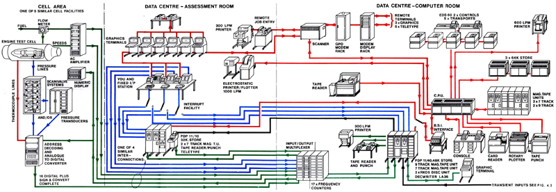
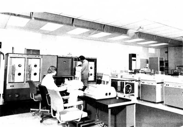
4.9 The Data Centre
The Data Centre at N.G.T.E. provides the main computing
capability for the Establishement and in particular the capability to collect, record,
assess and display data originating from the tests being implemented on the engines in
the test cells. Land lines run form the data rooms in each cell area to the
Data Centre and ecah cell data gathering
system is operated "on-line" in its turn by the computers located in the Centre.
THe mainframe computer is an International Computers Limited (ICL)
1904S* which provides a multiuser time-sharing system designed to allocate priority
to the operating test cell. A bureau service is available to other users and a number
of remote terminals are installed in various parts of the Establishment. Strict operating
and security procedures safeguard data integrity.
Two PDP 11 series computers supplied by Digital Equipment Corporation
Ltd. (DEC) complete the main computer hardware installation. A large number of VDU,
plotters, printers, punches and other peripherals are also available to allow the
maximum benefit to be obtained from the computer power available. Figure 4.1 shows
an outline of the overall Data Centre
organisation.
The first stage of data collection and distribution to and from the test
cells is implemented by a combination of the PDP 11/10 computer and the input/output
multiplexer. Any specific addressed channel can be digitised either once, or four or
eight times if a mean value of several samples is desired. The averaging process
is also implemented by the PDP 11/10 computer and the software for this machine
is written in FORTRAN IV RT11 V3 computer language.
|
|
Fig. 4.9 N.G.T.E. main computer room in the data centre
|
Software has been developed at N.G.T.E. to provide
a fast assessment "on-line" system of data presentation that includes tabular line-printer
output, VDU display with or without graphics option, and numeric display of calculated
data in the test cell control room. Collected data may be stored on paper tape,
magnetic tape or magnetic disc, thus providing a recoverable data source in the event
of system failure.
The present (1981) facility is designed to cope with up to 1000 discrete
addressable channels which are directly available to the computer. This limit will
be shortly increased to 1500. The data is collected in a parallel format providing 4.5
decades binary coded decimal (BCD) resolution. The normal scanning rate is approximately
100 channels/second and the overall time for each scan is dependent upon the number of
channels being scanned and the number of times each channel is digitised.
The tasks performed by the ICL 1904S* computer are under the
control of the ICL George Mk 8.64 operating system. THe program used to operate the
cells data gathering systems is known as FRED and has been developed at the
N.G.T.E. with the main objective of providing a complete set
of calculated and printed engine performance data in the assessment room area of the
Data Centre within two minutes of receiving
test print data from the cell. Six graphic VDU terminals are available in the assessment
room area and are provided with a hard copy facility.
4.10 Support Workshops
4.10.1 Introduction
Three workshops are available, each specialising in the particular
areas of electronics, instrumentaion and acoustics. The latter workshop serves the
Noise Test Facility which is not described in this publication.
4.10.2 The Electronics Workshop
The majority of all electronic units and systems in the test facility
pass through this workshop. AN acceptance inspection service is provided for new
electronic equipment prior to installation at its operational site. Likewise,
a co-ordination/inspection service is provided for equipment being returned for
repair of service to the original manufacturer.
This service includes all the work associated with claims under
warranty. The main tasks undertaken by the workshops are hower the testing to specification and the
repair and calibration of the wide variety of electronic equipment installed at
N.G.T.E.. The diverse nature of these units has given the
workshop broad experience in digital, analogue and hybrid circuitry as well as video systems
and magnetic tape recording equipment. Prototype construction and assembly is also undertaken,
as well as the installation and commissioning of equipment manufactured or purchased
by N.G.T.E.
4.10.3 The Instrument Workshop
The instrument workshop deals with all instrumentation equipment
other than electronic systems. This is a broad field covering mechanical, electrical and
pneumatic instruments as well as hybrid types in the precision and light engineering
class. Maintenance, calibration, installation and commissioning of these instruments
on both engine and plant systems is the major function of this workshop and encompasses
transducers, transmitters, signal conditioning equipment and readout/display devices.
Many differing requirements arise for the measurement of various paramters
in differing locations and enviroments. The instrument workshop has the capability to
fulfil these needs and is able, for instance, to manufacture most types and sizes of
thermocouple.
Repair of thermocouples and pitot pressure rakes is undertaken as is
the strain gauging of various components both stationary and rotating. Pressure calibrations
are also performed utilising the N.G.T.E. dead weight tester working
standard.
Heat treatment cyclind and curing is possible up to 400°C using
an oven which may also be used to check the function of apparatus at various environmental
temperatures within the specified limit.
© Procurement Executive, Ministry Of Defence
|