
|
|
|
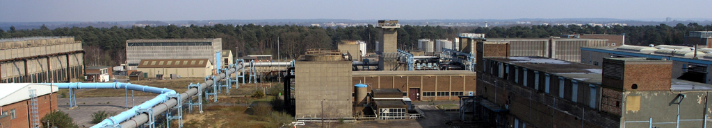
Engine Test Facilities
home | documentation | literature | plant and equipment for aerodynamic and combustion testing
|
 |
 |
Plant and Equipment for Aerodynamic and Combustion Testing
National Gas Turbine Establishment
Pyestock, Hants.
Whetstone, Leics.
Plant and Equipment for Aerodynamic and Combustion Testing by W. G. Fletcher and J. B. Lloyd.
This document is not a N.G.T.E. Report and is intended for the use of the recipient only. If, subsquently,
the contents seem likely to be of wider interest, they may be embodied in an official N.G.T.E. Report
or Memorandum.
|
- Introduction
This Note describes the provisions to be made on the N.G.T.E. centralised site for combustion and
aerodynamics research.
- Buildings
- Layout
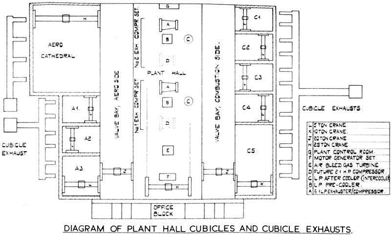
The layout consists of a central plant hall with annexes, on each side of which is a valve bay flanked by
a line of test cubicles (see Figure 1). The combustion cubicles exhaust to the site boundary. The valve bays
are designated by the cubicles they serve.
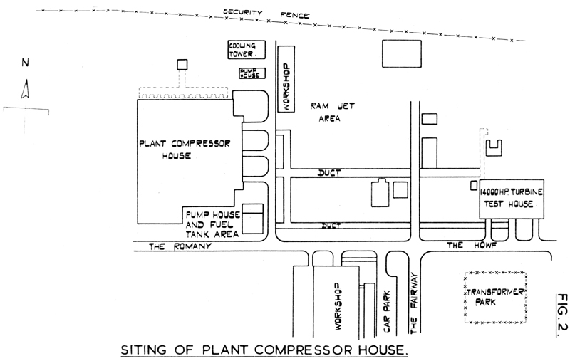
- Siting
The siting shown in Figure 2, meets the main requirements of future expansion and convenience in exporting
air to Ram Jet Plant and the
14,000 H.P. compressor test rig.
|
|
Figure 1: Diagram Of Plant Hall Cubicles And Cubicle Exhausts
|
|
|
Figure 2: Siting Of Plant Compressor House
|
- Compressor Plant
- General
The requirements are for exhauster and compressor capacity, and originally it was proposed to
provide separate plant for each duty but this provided to be financially beyond our means. These original
proposals are of interest and are shown in Table 1.
Suitable motor driven machines were sought capable of doing exhauster and compressor duty without bias in
respect of type. No centrifugal compressor was found but the Metropolitan-Vickers Locomotive compressor
seemed reasonable suitable when slightly modified to make the pressure ratio 6:1. An overall pressure ratio of
12:1 will be obtained at the cubicles by running in series with a high pressure 2:1 (nominal) centrigual
unit and provision is being made in the plant hall for a 2:1 machine adjacent to each of the 6:1
machines being provided initially.
The two 6:1 machines are intended for parallel operation when running with or without the 2:1 series compressor.
The leaving temperature of the 6:1 machines when working alone will be 250°C when compressing and
300° when exhausting. We shall design for a leaving temperature of 250°C from the 2:1 compressor
when operating in series with the 6:1 machine on compressing duty.
A full description of the main rotating machinery is given in Table 2, but briefly we shall be able
to supply 120 lb./sec. at 6 atmospheres or exhaust 17 lb./sec. from 1/6th atmosphere.
The next step will be the addition of the 2:1 series machines giving 120 lb./sec. at 12 atmospheres or
8.5 lb./sec. exhausted from 1/12th atmosphere. Ultimately these supplies may be doubled and wherever
practicable necessary provision for expansion has been made.
In addition a Parsons Air Bleed Gas Turbine set is being installed, to supply 25 lb./sec. of air
at a pressure ratio of 4:1 for special duties.
- Choice of drive for the main plant
Three forms of drive were considered in the planning stage, namely steam turbines, electric motors with
and without speed control, and gas turbines.
Steam turbines were found very attractive because of the availability of the boilers in the
14,000 H.P. test plant, but were rejected because of the
large quantities of water required for condensing purposes.
Gas turbines could not compete on cost, and further, since no suitable unit existed, a major development
project was involved, which could not be contemplated.
The choice therefore fell to the electrical drive, with the power station
supplying the base load. Speed control was rejected because of the increasing cost and doubtful advantages.
Inlet and outlet throttling will perform most of the function of variable speed.
- Plant Control Room
All the electrically driven plant can be started and completely operated from teh control room which
is situated at the extension (west) end of the plant hall. Control desks are provided for each of the 6:1
exhauster compressors, for the motor alternator set, and for the Air Bleed Gas Turbine.
A diagram of the air distribution system is incorporated in the control desks, and any wrong operation
or positioning of the valves during starting up or running will be revealed by a warning signal. The incorportation
of a system of interlocks will prevent damage to plant and/or personnel due to incorrect operation.
Dummy panels will be left for the future incorporation of the 2:1 series compressors.
The control wroom will cater for a further line of control desks over-looking the future extension of
the plant hall.
- Air delivery system
- Pressure air
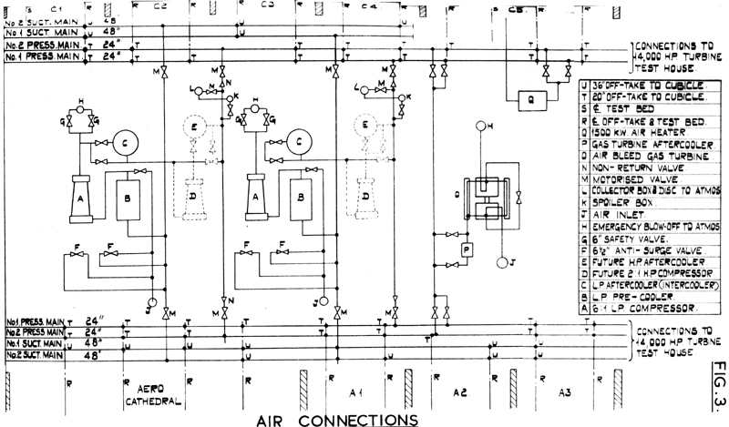
Each exhauster-compressor will feed via its aftercooler and by-pass into 24 in. mains either on the Aero. or
Combusion side of the Plant House so there are two 24 in. mains through both the Combustion and Aero.
valve bays (Figure 3). If the two furtehr exhauster-compressors are installed the same mains will be used so that each
main will be fed by two compressors. The maximum velocities appropriate to these various conditions are shown
in Table III.
|
|
Figure 3: Air Connections
|
Table III
| 50°C |
250°C |
50°C |
250°C |
50°C |
250°C |
50° |
250°C |
| 46.8 |
75.6 |
23.4 |
37.8 |
93.6 |
151.2 |
46.8 |
75.6 |
A compromise is evident between cost of pipes and pressure loss but in most cases the velocities are reasonable and
if pressure loss is of particular importance at the 6:1 condition, where the velocities are a maximum, then the
2:1 high pressure machines can be brought in as boost.
- Exhausted air
There are many cases in which hot exhaust products will have to be cooled before entering the exhausters.
Three gas coolers will be provided, to be installed at the cubicles, each of whic his capable of cooling the
air duty of one machine from 1,000° to 250° at any pressure within the range 1 atmosphere downwards. The air
will pass through the main ductwork at 250°, thence through the pre-cooler and into the exhauster at 50°.
A similar system with regard to the possible future machines would apply, so that each valve bay would have two
48 in. diameter suction mains each feeding two exhausters. The maximum velocity when feeding one machine with
250° air is 110 ft./sec.; here the above mentioned compromise is more evident than in the case of the 24 in. diameter
mains. In teh case of cold exhaust at 50° the maximum air velocity will be 68.6 ft./sec.
- Cubicle feeds
The method of feeding the air to the cubicles will be evident from the accompanying diagrams. The air rises vertically
from the valve bay mains through the stop/throttle valve and into the meter, heater or other plant housed in the valve
bay, and thence into the cubicle. A modest number of 20 in. motorised valves will be available for cubicle feeds,
and when a test bed is not in use the branch on the air main will be blanked.
- Air temperature control
An aftercooler and by-pass will be provided for each machine and temperature control will be possible between
50°C and 250°C approximately in the cast of the exhauster compressors, and between 50°C and 170°C approximately,
in the case of the air bleed gas turbine.
Further heating beyond the delivery temperature of the compressor will be provided electrically. Initally when
4:1 compressors were proposed the heater was to be placed in parallel with the cooler (i.e. a heater in the place
of the cooler by-pass) giving air temperatures between 50°C and 325°C this air being taken through the main pipework
to the cubicles. In the present design the leaving temperature from the 6:1 machines is 250°C and the heating will
be provided on two test beds up to 400°C but air at this temperature will not be passed through the
main pipework. This change is necessary because pipe sizes, expansion problems and costs get out of hand with the present
larger flows and higher temperatures.
The leaving temperature from the electric heater will be automatically maintained after preselection. Teperature
selection will be made at the cubicle by the test engineer. A total of 3,000 K.W. is available for heating,
delivered by two 1,500 K.W> alternators, each delivering separately to a 1,500 K.W. heater. Control is obtained by
operation on the field of the pilot exciter. Control of temperature to the limits of +/- 2½°C is specified
throughout the whole range.
Where higher temperatures are required or greater mass flows have to be heated, or put more generally, where greater
heat bulk is required, heat exchangers will be installed in the valve bay.
- Export of air
The above figures of velocities in the mains apply only when the air is being fed to cubicles. If pressure air is being
exported, say to the Ram Jet Plant and
14,000 H.P. compressor test rig, all the 24 in. mains on both sides of the
building will be used. The maximum velocities obtainable if the two additional exhauster-compresor sets are installed
will be as indicated in Table II under the head "One Machine".
In the case of the vacuum mains only two will be used for export, but the air will be cooled to 50°C. at the user
end, giving a maximum velocity of 132 ft./sec.
- Cooling water systems
There are three main cooling water systems as follows:-
(a) for the plant, (b) for the test side, and (c) for exhaust cooling.
- Plant cooling
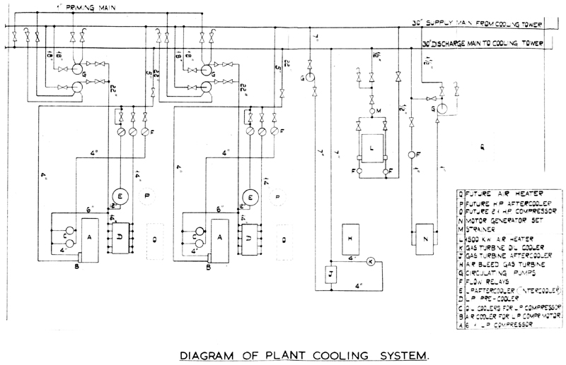
The plant cooling system is shown in Figure 4. Two 30 in. mains, inlet and return, run along the combustion side
of the plant hall. Flow along the supply main is by gravity. Each exhauster compressor set is provided with two
main circulating pumps, which circulate water from the inlet main through the plant coolers, and thence through
the discharge main to the cooling tower. The mains are designed for a temperature range of 86°F to
107°F and a water velocity not exceeding 5 ft./sec.
|
|
Figure 4: Diagram Of Plant Cooling System
|
At a later date the two mains will continue through the extension of the building to another cooling tower,
thus giving the benefit of a ring main and keeping the pip sizes to manageable proportions.
- Test cooling
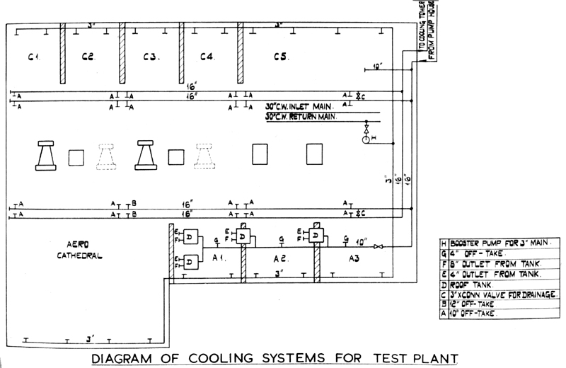
Figure 5 shows the Test Cooling System which will provide water for (a) large duty cooling and (b) small duty cooling.
|
|
Figure 5: Cooling Systems For Test Plant
|
- Large duty
Two hundred and forty thousand gallons per hour at 110 feet head will be available in the valve bays and cubicles
from 16 in. flow and return mains which run along the valve bays. A 10 in. tapping will run over the cubicle roofs
to supply constant head tanks, etc. for use with hydraulic brakes. The water will be pumped direct from the cooling
tower pond, and will be available at all points en route without further pumping. When used in the gas coolers,
the water quantity is capable of cooling 120 lb/sec. of air from 1,000°C to 250°C.
- Small duty
4 in. tappings, taken from the 10 in. pipe on the cubicle roofs, will provide cooling water to small plant, such as
oil coolers, with flows of up to 9,000 gallons per hour.
- Exhaust cooling
To protect the rig exhaust systems from damage it is necessary to inject water to cool the exhaust products. A
3 in. pipe supply at 250 lb/sq. in. will be provided for this service, and will run through all the cubicles
on both the Aero. and Combustion sides (see Figure 5). The maximum quantity available will be 30,000 gallons per hour
and the available pressure will ensure good atomisation and penetration of the
water at the maximum test chamber air pressure of 12 atmospheres.
- Cooling towers
The cooling towers are of reinforced concrete. They are of square section for operation on the induced draught system.
Two cells are provided, one for high temperature cooling and one for the plant exhauster compressors.
The high temperature tower operates with the gas coolers and has a flow of 240,000 gallons per hour with a temperature range
187° - 100°F. This water is treated to reduce the total hardness to 6°.
The water flow in the plant cooling tower is 273,000 gallons per hour and the temperature range is 107°F. to
86°F. This water flow caters for all the machines at full load on compressing duty. When performing exhauster duty
the quantity of water is increased but the temperature range is much lower.
- Test cubicles
- Combustion side cubicles
Figure 1 shows a plan layout of the cubicles, consisting of four cubicles 30 ft. x 40 ft. x 30 ft. high, and one cubicle
75 ft. x 40 ft x 30 ft. high. In the small cubicles hand-operated five-ton cranes will be provided, and the large cubicle
will be equipped with a ten-ton hand crane.
- Aero. side cubicles
The Aero. cubicle facilities consist of The Cathedral, 90 ft. x 70 ft. x 54 ft. high, two cubicles 30 ft. x 40 ft. x 30 ft.
high, and one cubicle 45 ft. x 40 ft. x 30 ft. high. The Cathedral will be equipped with a twenty-five ton hand-operated
crane whilst the three smaller cubicles will have five-ton hand-operated cranes.
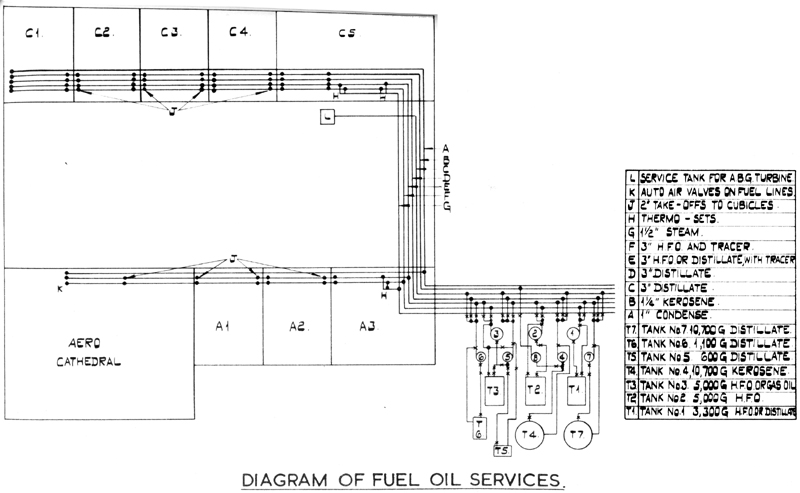
- Cubicle fuel systems
- Combustion side
Fuel will be conveyed to all cubicles by boost pumps at the day tanks. No header tanks will be provided. Four lines
will enter each combustion cubicle terminating at 15 feet below ceiling level. Two lines will be heated, and the tracer lines
will terminate at blank flanges in the cubicles so that steam may be used for further heating in the cubicles. All
fuel lines will terminate at stop cocks, which can be operated from outside the cubicle.
- Aero side
The Aero side cubicles will be fed by two heated lines.
|
|
Figure 6: Diagram Of Fuel Oil Services
|
- Access to cubicles
Access for personnel will be provided at ground level from the valve bay and the concrete apron in front of the cubicles.
Communication will be provided between the cubicles by self centring doors, which, being without fastenings, are
easily opened in case of emergency. Any point in the cubicle will be served by two exits which can be reached
without climbing over the rigs, so that escape will be difficult only in the rare case of fire occurring in more
than one place at the same time or on the direct spot where a person is standing, thus enveloping him.
- Observation rooms
In addition to the above, a walk-way in teh valve bays at the fifteen foot level will serve a mezzanine floor in the
cubicles which will carry the observation room. (This floor will be removable). This is regarded as the normal
position for the observation room, but it will be possible to erect observation points on the cubicle floor in cases where
this is necesssary.
- General
All cubicles on both the Aero. and Combustion side will be provided with silenced air intakes for 60 lb/sec. In the case
of the Aero Cathedral the air quantity is 120 lb/sec.
The beds provided in the cubilces will consist of reinforced concrete beams with broad flange rolled steel joists
in the top surface capable of absorbing 90 tons load at 3' 6" centre height. These will considerably ease test bed
erection problems and will enable shut off valves (which give rise to fluid loads) to be installed on the beds.
The main access doors to the small cubicles with be 8 ft. wide and 12 ft. high approximately.
At all times free access to the atmosphere will prevent structural disintegration of the cubicle due to differential pressures.
Without such a provision a cubicle 30 ft. x 30 ft. x 40 ft. would be destroyed in a few seconds if air from both
compressors was fed into it.
Sound absorbing material will be used as a cubicle lining above the 15 ft. level.
A load carrying beam is incorporated in the front and back walls of the cubicles at the fifteen foot level. This beam
is capable of carrying the super structure, so that the cubicle walls between stanchions may be completely removed
below the fifteen foot level.
In the side walls of the cubicles at the fifteen foot level are exposed beams with drilled webs enabling floors or other
super structure to be erected as required.
- Silencing
- Air intakes and exhausts for the fixed plant
Silencing of the exhausts will be achieved by splitter panels enclsoed in a mild steel box incorporated in the
exhaust duct. This box is below the roof level, and although a certain amount of noise will penetrate the
3/8 ins. walls of the duct into the plant hall the system is effective as far as noise to atmosphere is concerned.
The air intakes incorporate splitter units and filters, which hare housed within the structure of the building above
the annexe between the plant hall and valve bays.
The anti surge blow offs discharge into very robust steel boxes securely anchored, and from there to atmosphere through
the exhaust splitters. By this means the energy contained in the jet is safely dissipated with the minimum of
external noise.
- Cubicle exhausts
The cubicle exhaust system is illustrated in Figure 1 and consists of an underground duct running along the length of the
cubicles with branches of reduced diameter connecting to each bed. The diameter of the main duct is 8ft. with branches
varying from 2 ft. diameter on the combustion side to 4 ft. diameter in the Aero Cathedral. These main ducts terminate in
vertical steel stacks encased in masonry and containing splitter banks. (The ideal system would provide a separate
exhaust for each bed, thus avoiding interference between the adjacent exhausts, and would also, by keeping the
stored volume to a minimum reduce the severity of an explosion should one occur. Such a system is, however,
much too costly and could not be provided).
Water will be injected into the exhaust stream to reduce the gases to a safe temperature.
Table I Historical
Machines initially proposed for installation in the Plant Hall
| 1 |
4,000 H.P. Turbo-compressor with induction motor drive having 70-100% speed control by rotor resistance |
To supply 25 lb/sec of air at 4 atmospheres pressure. |
11 K.V. main circuit breaker.
Aftercooler and air heater.
Gears.
Rotor resistance. |
|
| 2 |
4,000 H.P. Turbo-compressor with induction motor drive having 70-100% speed control by rotor resistance |
To supply 25 lb/sec of air at 4 atmospheres pressure. |
11 K.V. main circuit breaker.
Aftercooler and air heater.
Gears. |
|
| 3 |
2,200 H.P. Turbo-compressor with induction motor drive, taking the delivery from machine No. 2. |
To supply 25 lb/sec of air at 10 atmospheres pressure. |
11 K.V. main circuit breaker.
Liquid starter.
Gears.
Intercooler between machine No. 2 and this compressor. |
The Plant House will incorporate the foundations for a similar unit adjacent to machine No. 1. |
| 4 |
Air bleed gas turbine. |
To supply 25 lb/sec of air at 4 atmospheres pressure. |
Electric motor for starting the set, with switches and starting gear.
Aftercooler. |
|
| 5 |
2,000 H.P. Turbo-compressor with induction motor drive having 70-100% speed control by rotor resistance |
To exhaust 10 lb/sec of air from 1/6 atmosphere. |
11 K.V. main circuit breaker.
Rotor resistance.
Gears. |
|
| 6 |
2,000 H.P. Turbo-compressor with induction motor drive having 70-100% speed control by rotor resistance |
To exhaust 10 lb/sec of air from 1/6 atmosphere. |
11 K.V. main circuit breaker.
Rotor resistance.
Gears. |
|
| 7 |
600 H.P. Turbo-compressor with induction motor drive. |
To exhaust 10 lb/sec of air from 1/12 atmosphere and deliver it to machine No. 5. |
3.3 K.V. main circuit breaker and starter.
Aftercooler for use when running with machine No. 5.
Gears. |
|
| 8 |
600 H.P. Turbo-compressor with induction motor drive. |
To exhaust 10 lb/sec of air from 1/12 atmosphere and deliver it to machine No. 6. |
3.3 K.V. main circuit breaker and starter.
Aftercooler for use when running with machine No. 6.
Gears. |
|
| 9 |
4,000 K.W., 11 K.V. synchronous motor driving 2 x 2000 K.W. low voltage alternators. |
To provide low voltage current for air heaters, with secondary use as a synchronous condensor for p.f. correction. |
Either - starting motor with control gear, or, if the alternator is wound as a synchronous induction motor, main circuit breaker and liquid resistance. 2 x 2,000 K.W. electric heaters. |
Three other heaters will be provided in the cubicles and valve bay. |
| Notes |
(a) Maximum quantity of 4:1 air is 75 lb/sec. from machines 1, 2 and 4 in parallel.
(b) Maximum quantity of 10:1 air is 25 lb/sec. from machines 2 and 3 in series.
(c) Maximum suction from 1/6 atmosphere 20 lb/sec. with machines 5 and 6 in parallel.
(d) Maximum suction from 1/12 atmosphere 20 lb/sec. with machines 5 and 7 in series running in parallel with 6 and 8 in series. |
Table II
New Site - Plant Hall Equipment
| 1 |
Motor alternator set. 11 K.V. synchronous motor driving the 440 volt 3 phase 1500 K.W. alternators through double shaft extension, equipped with pilot and main exciter. Free circulation bottom entry top discharge cooling system (Metropolitan Vickers) |
To supply low voltage power for electric air heaters. |
11 K.V. circuit breaker.
Low voltage heater selection panel.
Sheathed wire element electric heaters in 1500 K.W. units.
Temperature selection boards and plant for automatic maintenance of temperature. |
For air heating up to a maximum of 400°C normally, but up to 5000°C by special stainless steel heater unit. To provide power for electric heaters on R.J. project. |
| 2 |
Air bleed gas turbine, 2700 H.P. bled air. (C.A. Parsons) |
To supply 25 lb/sec. of air at 4 atmosphere pressure and temperature range 50°C - 170°C. app. |
33 K.V. starter motor.
Aftercooler.
Askania regulator. |
|
| 3 |
8850 H.P. axial flow compressor driven by 3 phase 11 K.V. salient pole synchronous motor through step up gears. Closed circuit air and water cooling system. |
To deliver up to 60 lb/air/sec. at pressures up to 6 atmospheres. COntrol of delivery pressures by inlet throttling. Delivery temps. within the range 50°C - 250°C. Alternatively this m/c will exhaust 8.5 lb/sec. from a pressure of 1/6 atmosphere minimum. |
Precooler and aftercooler.
11 K.V. switchgear.
Askania regulator.
Korndorffer auto transformer starting equipment. |
Foundations will be laid in the plant hall for the installation of a 2.1 (nominal) series compressor on the high pressure end to give pressure ratio of 12 for exahuster and compressor duty. Mass flow unaltered. The present aftercooler becomes an intercooler and an aftercooler is installed after the 2:1 machine. This combination to be called the No. 1 set. |
| 4 |
As 3 above. |
As 3 above. |
As 3 above.. |
As 3 above, but to be known as No. 2 set. |
Maximum quantity of 6:1 air 120 lb/sec.
Maximum quantity of 4:1 air 25 lb/sec. |
|
|