|
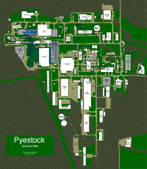
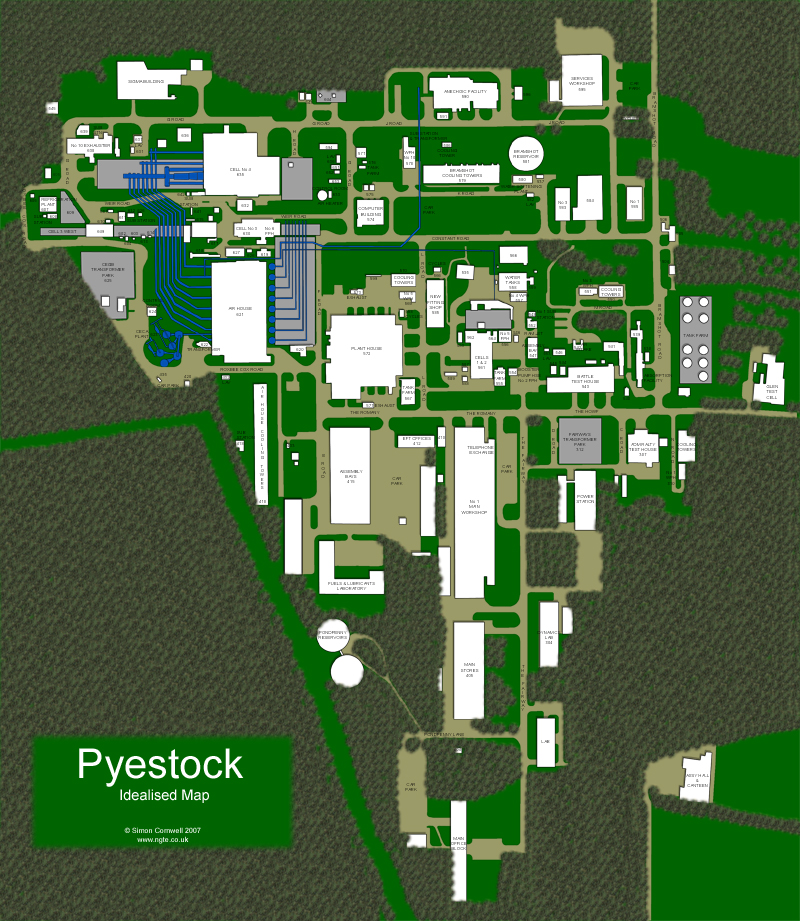
Map: Pyestock 2002-2007
© Simon Cornwell 2007
I needed a general plan for this website. A specific plan wouldn’t have done as it would’ve been a snapshot
in time, with some buildings yet to be built, and others doomed for demolition. So I created the Idealised Map
which shows all the buildings of Pyestock which existed between 2002 and 2007.
The map was put together from multiple sources: satellite images (which already showed a number of
changes between themselves), plans photographed at Pyestock, my pictures of the site and illustrations in
Ian McKenzie’s book.
All the buildings were identified by three digit numbers which have been reproduced here, as well as the
more informal names given to many of the larger buildings and test cells.
The Assembly Hall And Canteen was part of the Old Pyestock site, and was swept
away when the remaining buildings were demolished for a new QinetiQ development in 2002.
A new road was driven through the southeast quadrant at the same time requiring the demolition of
the Main Office Block and the southern Laboratory.
The GLEN Test Cell was sold in 2003. The contents were removed and the building was demolished.
In later years, the Sigma Building and Fuels & Lubricants Laboratory were added to the
site, contributing to the ebb and flow of buildings and structures. So whilst the Idealised Plan
shows all these structures together, they never all existed at the same time.
|
|
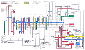
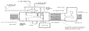
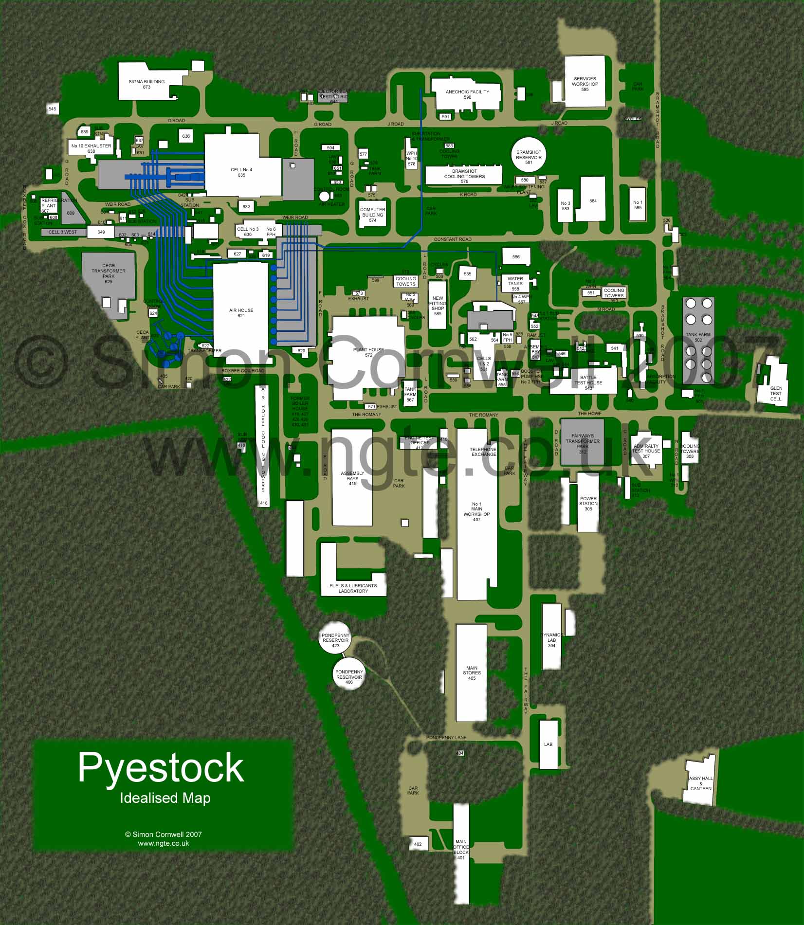
Plan: Air Supply Plant N.G.T.E. Old Site (1974)
© Procurement Executive, Ministry Of Defence
I've included this schematic for completeness as it shows the Air Supply Plant and test
laboratories of the N.G.T.E. Old Site. This was demolished before our explorations began.
It shows how the design of the Plant House was
probably based on a similar design.
|
|
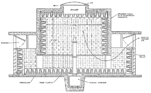
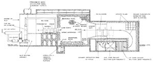
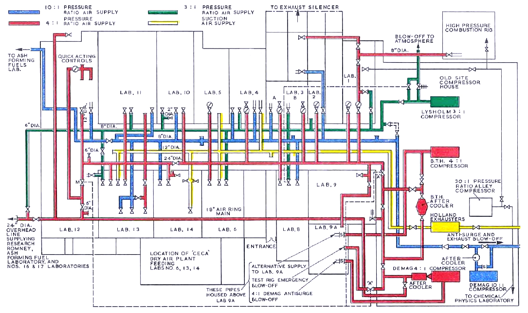
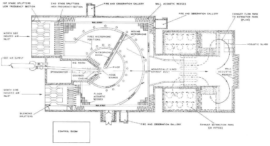
Plan: Anechoic Chamber N.G.T.E. Old Site (1974)
© Procurement Executive, Ministry Of Defence
This is a schematic of the Anechoic Chamber on the N.G.T.E. Old Site. It was demolished before our explorations began.
|
|
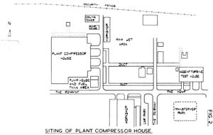
Plan: Siting Of Plant House (1954)
© Ministry Of Supply
This early plan of Pyestock was found
in a document in the Plant House
and photographed in-situ.
It shows the siting plan for the Plant House. Notice how the security fence shows the original
size of the site, the original name of Battle Test House and the space left for the
Ram Jet Area (which became Cells 1 & 2).
|
|
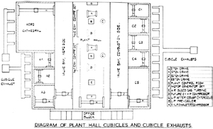
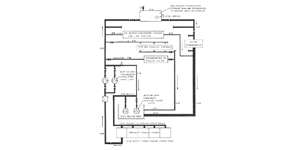
Plan: Plant House (1954)
© Ministry Of Supply
We also photographed this plan of the Plant House from the same document (see above).
This clearly shows the internal organisation of the building, with its large central plant hall, and combustion and aerodynamic testing
chambers along each side.
Unfortunately the top of the plan has been lost, but showed the Plant Control Room and a note: Extension End Of Plant House.
It was forseen in 1954 that the Plant House would require extending and provision was made;
however, the Air House was built instead, and the Plant House
remained unextended.
|
|
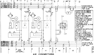
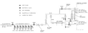
Plan: Plant House Air Supply (1954)
© Ministry Of Supply
The air supply in the Plant House was produced by two Metrovick compressor/exhauster sets and a Parsons Air Bleed
Turbine. This diagram shows how the plant was arranged to produce several pressure and sunction mains for the aero and combustion
cubicles in the Plant House itself, and for connecting to external test areas.
|
|
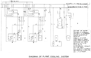
Plan: Plant House Diagram Of Plant Cooling System (1954)
© Ministry Of Supply
The plant and anciliary equipment required cooling and this schematic shows how the plant in the Plant House
was connected to its
own cooling tower.
|
|
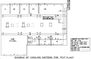
Plan: Plant House Diagram Of Test Plant Cooling System (1954)
© Ministry Of Supply
The equipment being tested in the test rigs also required a cooling supply. This schematic shows how cooling reserves
were taken from tanks in the roof of the Plant House, before it was circulated around the plant under test (with attachment
points in each cubicle) and the cooling tower.
|
|
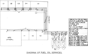
Plan: Plant House Diagram Of Fuel Oil Services (1954)
© Ministry Of Supply
The equipment being tested in the test rigs of the Plant House also needed fuel. This schematic shows how a network
of fuel lines (of different fuels) could be pumped to test rigs in any of the Plant House's cubicles.
|
|
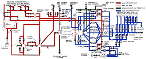
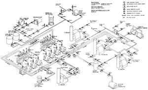
Plan: Plant House Diagram Of Air Main And Rig Connections (1974)
© Procurement Executive, Ministry Of Defence
This schematic was published about twenty years after the original Plant House literature and shows just how
complex the air supply and various connections to the testing cubicles had become.
|
|
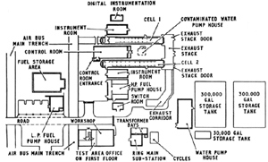
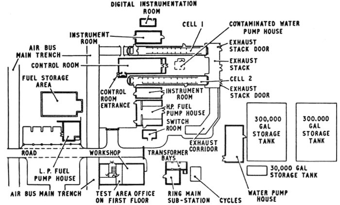
Plan: Cell 1 & 2 (1981)
© Procurement Executive, Ministry Of Defence
Cell 1 & 2 is one of the most confusing structures on the site: the
cells are buried under a tangle of pipes and ducting, the control room is housed in a concrete bunker, the
area is littered with small buildings and pump houses, all crowned by the dominating exhaust stack.
This plan clearly shows the component parts of the cell without getting overcomplicated by the various air,
water and fuel supplies routed around, under and over the various buildings.
|
|
Plan: Cell 3 West (1981)
© Procurement Executive, Ministry Of Defence
Cell 3 West is also a complicated structure. Whilst the cell and its
associated control room are relatively free of obscuring piping and ducting, the cell has several unique
ancillary support structures: the condenser and evaporator, the refrigeration plant and the cold store tanks.
The location of these can be clearly seen on this plan.
|

|
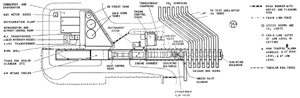
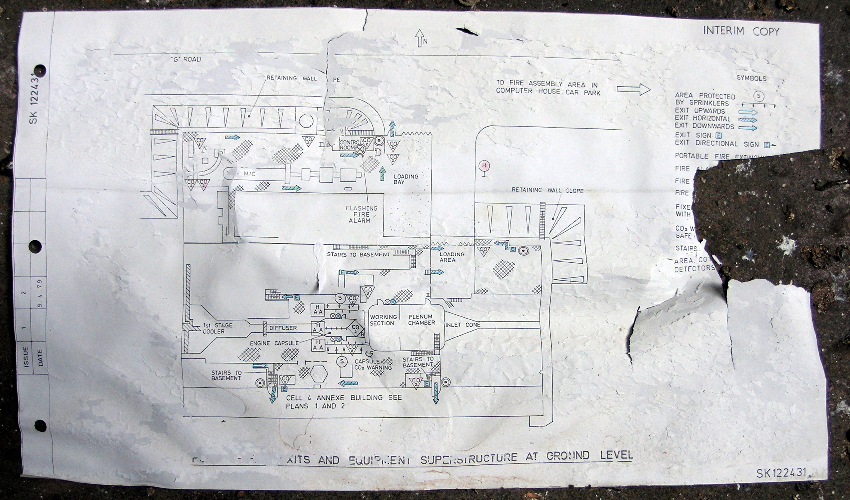
Plan: Cell 4 And Annexe
© Pyestock
This grotty plan was found in Number 9 Exhauster, the annexe to
Cell 4.
It was photographed in-situ and shows the layout of Cell 4 and its
relationship with Number 9 Exhauster which was built to the north of
the cell.
|
|
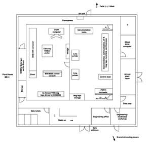
Plan: Computer Building - Ground Floor (1967-77)
© Mike Hatch 2008
"I spent almost 10 years at Pyestock starting as an apprentice, going on to
work in Cells 1 & 2,
Cell 3,
Cell 4 and the
Computer Building. I was an electronics
technician covering fuel systems, telemetry, data acciquisition in those
cells and eventually computers in building 574."
"The Computer Building (574) housed 4 computers, the mainframe machine an
SDS9300 and three others, a Digital Equipment Corporation PDP-7 Sn#41,
another DEC machine a PDP11/20 and an old for that time Elliott 803B (Bought
by the Ministry of Public Buildings. Various in-house built systems
connected these machines to the cells monitoring engine runs. Before these
computers there was a large valve computer possibly an Atlas but it was
decommissioned to be replaced with the SDS9300 just before I started there."
"The building appears to have been somewhat re-developed since my time there
(1967-77), as I do not remember the row of two storey offices fronting the
ramp to Cell 3 and
Cell 4, the main entrance to the building was the other side
opposite the Bramshott Cooling Towers. The roof in those days was flat not
pitched as seen in your pictures. I was responsible along with others in
shift teams for the day-day maintenance of the computers and ancillary
systems. Data prep for the computers was on punch tape and 80 column cards
using Teletype KSR33's, ASR35's and various paper tape systems."
"I've come up with a reasonably detailed drawing of that building floor and the
computer layouts. I don't recall the control room for Cell 3
being there as detailed on your website but that probably came with the
addition of the rear offices and new roof in later years." - Mike
|
|
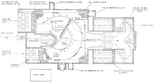
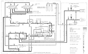
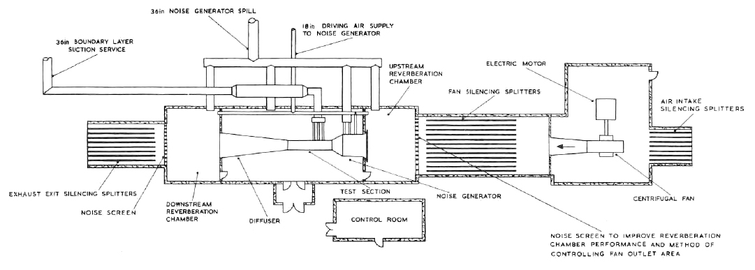
Plan: Noise Test Facility Absorber Rig (1975)
© Procurement Executive, Ministry Of Defence
This plan clearly shows the layout of the Noise Test Facility Absorber Rig and its associated control room.
|
|
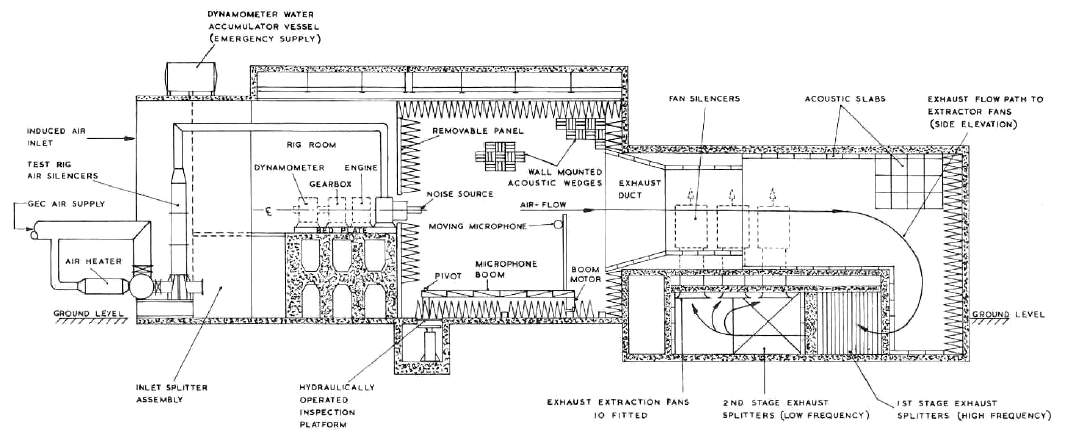
Section: Anechoic Chamber (1975)
© Procurement Executive, Ministry Of Defence
This shows a section through the massive Anechoic Chamber which stands on
the northern edge of the site, and is one of the buildings still in use.
|
|
Plan: Anechoic Chamber (1975)
© Procurement Executive, Ministry Of Defence
This is the ground floor plan of the massive Anechoic Chamber which stands on
the northern edge of the site, and is one of the buildings still in use.
|
|
Schematic: Anechoic Chamber Cooling Water Circuits (1975)
© Procurement Executive, Ministry Of Defence
The schematic shows the water flows through the Anechoic Chamber and the
Bramshot Cooling Towers.
|
|
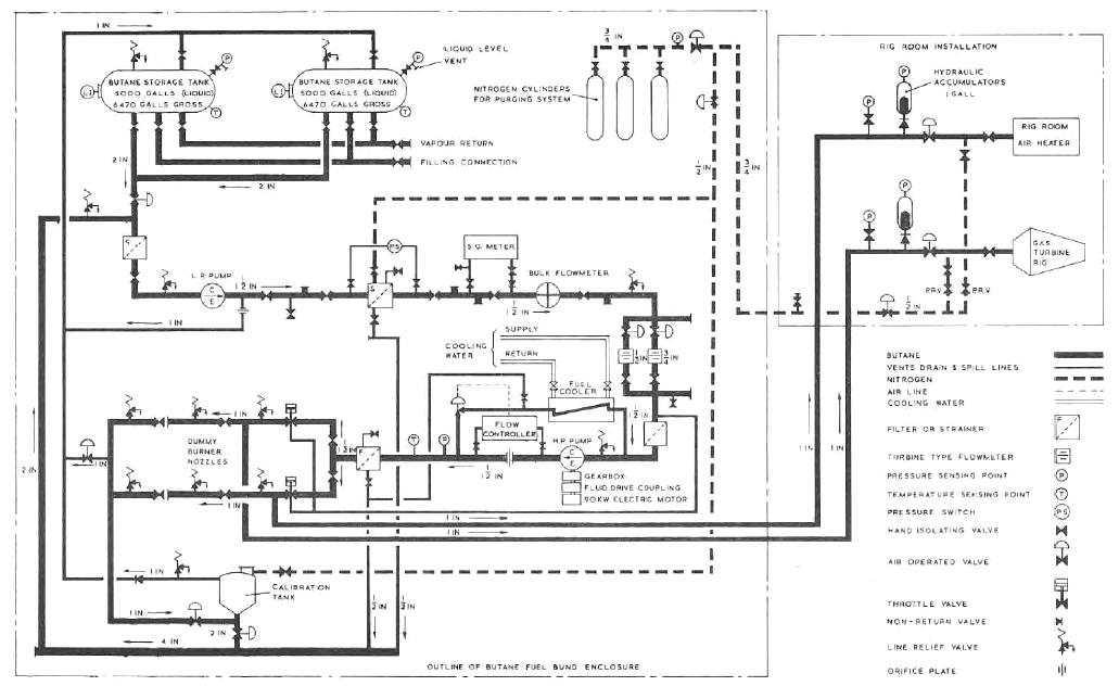
Schematic: Anechoic Chamber Fuel System Circuits (1975)
© Procurement Executive, Ministry Of Defence
The complex fuel distribution through the Anechoic Chamber is described in
this schematic.
|
|
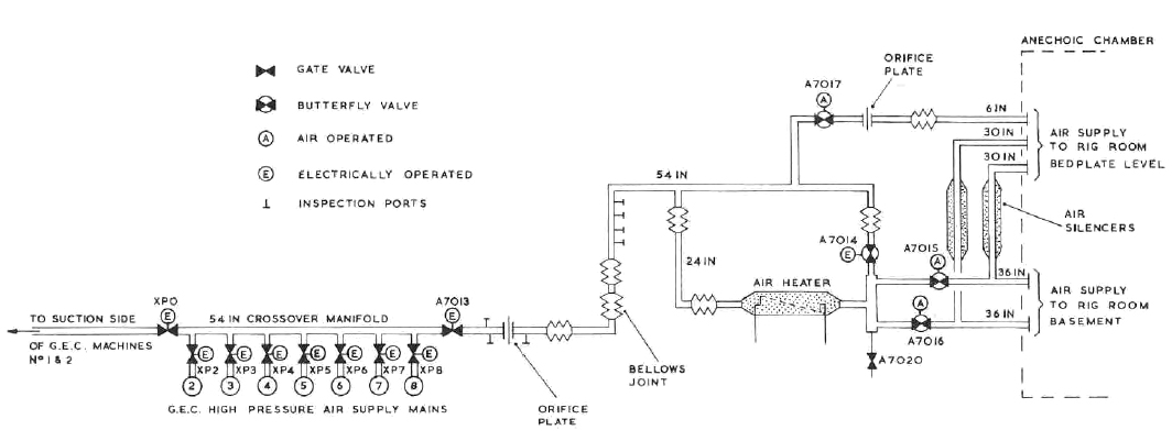
Schematic: Anechoic Chamber Air Supply (1975)
© Procurement Executive, Ministry Of Defence
The simple air supply facilities for the Anechoic Chamber when it
was originally connected to the Air House are described in
this schematic.
|
|
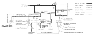
Schematic: Anechoic Chamber Air Heater Control System (1975)
© Procurement Executive, Ministry Of Defence
The steam and heater arrangements in the Anechoic Chamber are
described in this schematic.
|
|
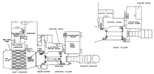
Plan: Glen Test House (1981)
© Procurement Executive, Ministry Of Defence
The GLEN test house was one of the first structures to disappear from Pyestock. After the
closure of the site, the test cell was sold in 2003 to Score’s repair and maintenance facility
near Peterhead, and the building itself was completely demolished.
The plans clearly show the layout of the ground and first floors of the former building.
|
|
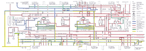
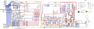
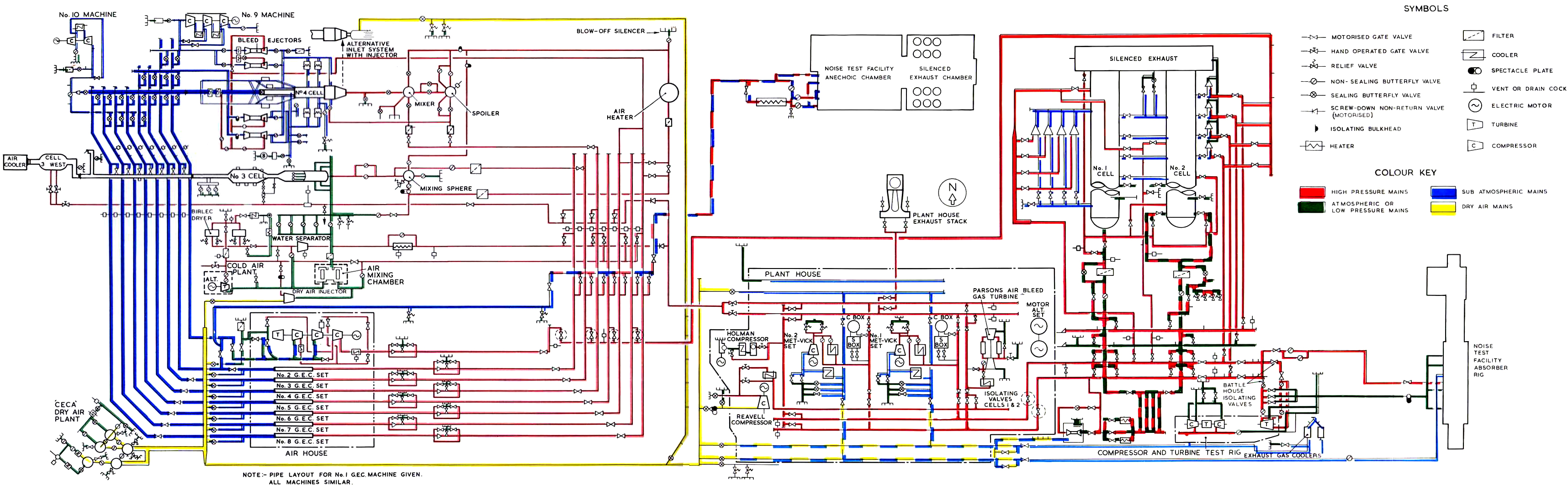
Schematic: Air Distribution Network (1981)
© Procurement Executive, Ministry Of Defence
The air supply was probably the most important network at Pyestock, circulating air to
the various test cells dotted around the site. The huge air pipes emanating from the Air House
was one of the iconic images of Pyestock, clearly visible in various aerial views.
This schematic shows the total extent of the air supply network from its humble beginnings in the
Plant House through to the sprawling, parallel flows through the
Air House.
Copies of this schematic were found in the Air House,
Plant House and
Computer Building, further underpinning how air flows were
extremely important to the functioning of the test cells.
|
|
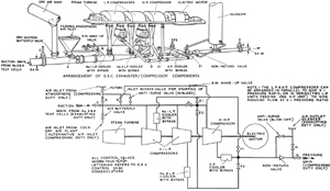
Schematic: Air Distribution Through GEC Exhauster/Compressor (1981)
© Procurement Executive, Ministry Of Defence
Each of the GEC compressor/exhauster sets in the Air House worked as
either compressors and/or exhausters, providing a range of pressures and air flows. Whilst the compressor/exhausters
could be connected together in various ways, each compressor/exhauster itself was sufficiently complex to merit this diagram.
|
|
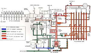
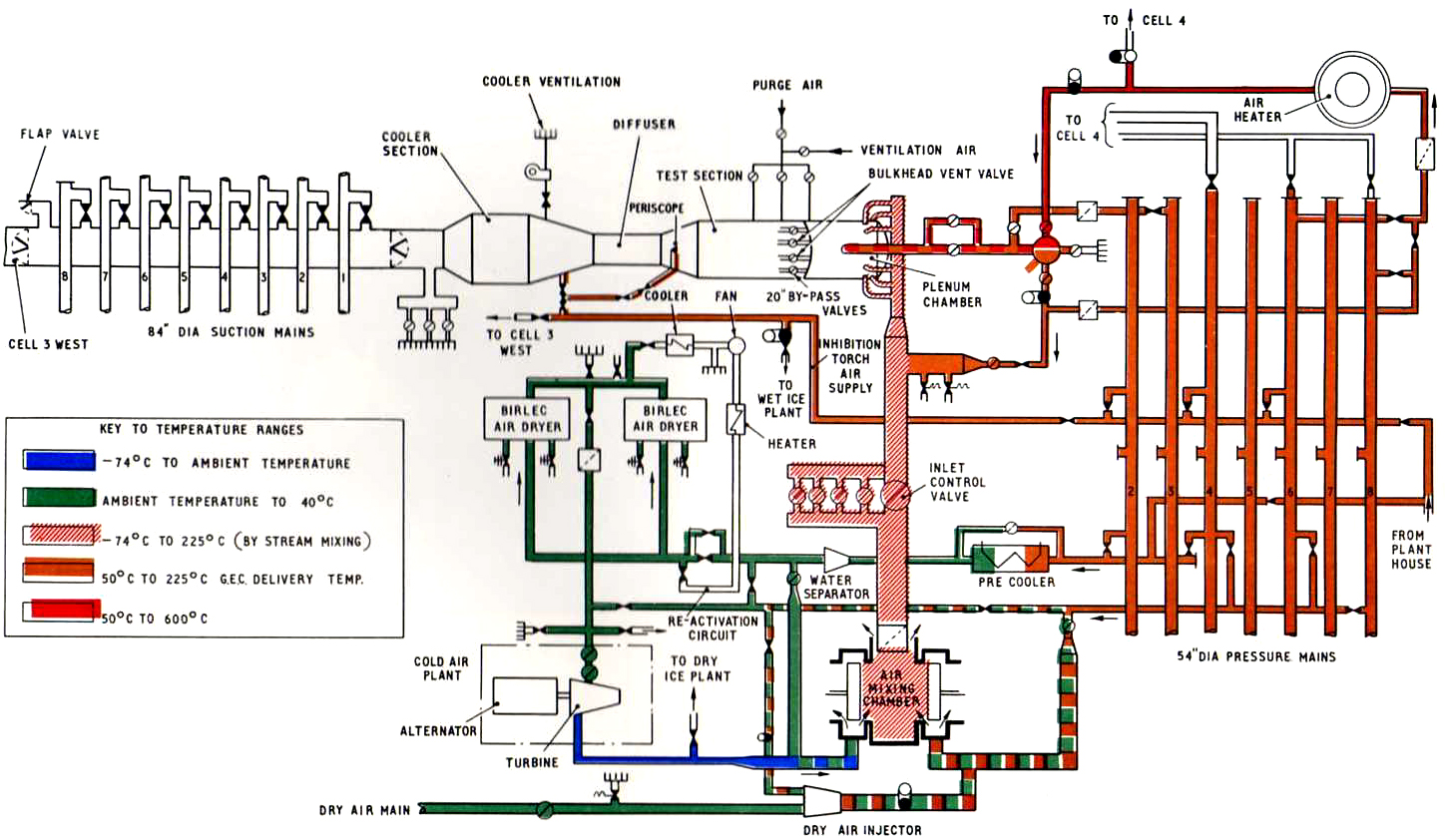
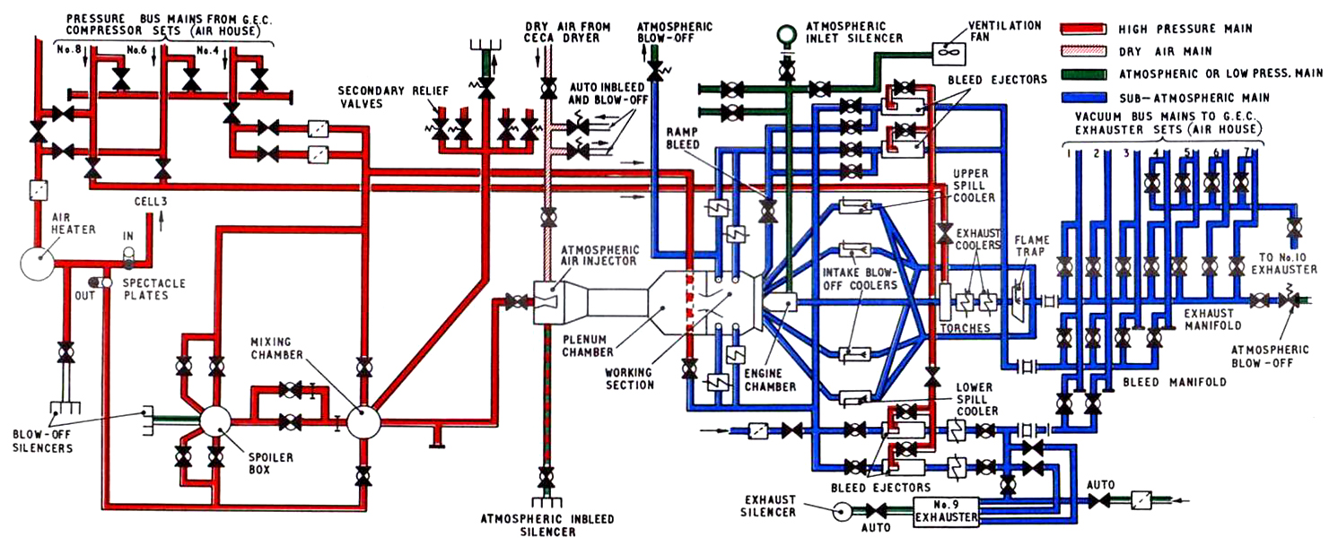
Schematic: Air Distribution Through Cell 3 (1981)
© Procurement Executive, Ministry Of Defence
With most of Cell 3 being submerged in a trench, it was easy to overlook the huge amount
of plant connected to it.
As shown in this schematic, the Cell was not only connected to the high pressure and suction mains from
the neighbouring Air House, but a complex arrangement of pipes and valves
connected the cell to various air dryers and heaters.
All this plant was squeezed in the narrow gaps to the south and east of the building.
|

|
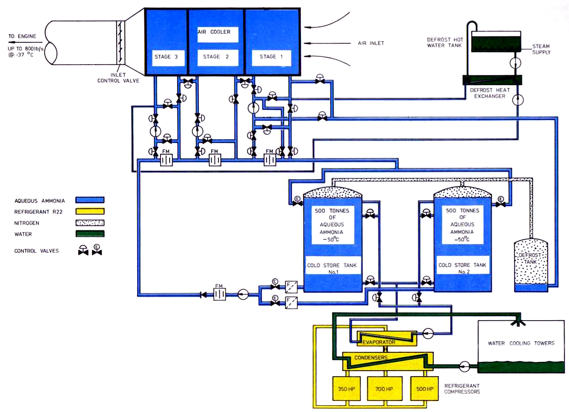
Schematic: Cell 3 West Cold Air System (1981)
© Procurement Executive, Ministry Of Defence
This schematic shows the sheer amount of plant (including two 500 tonne tanks of aqueous ammonia) required
to provide freezing air flows to the air cooler and eventually the test cell itself.
|
|
Schematic: Cell 4 Air System (1981)
© Procurement Executive, Ministry Of Defence
Cell 4 was massively complicated as this schematic of all the
high pressure and suction mains shows. All of this piping was above ground, adding to the already huge
bulk of Cell 4 itself.
|
|
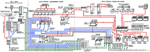
Schematic: Steady State Acquisition System (1981)
© Procurement Executive, Ministry Of Defence
Whilst engine tests were being performed, a huge amount of data was collected by various sensors in the cells and
sent to the Computer Building for collection and analysis.
This diagram not only shows the connections between a test cell and the Computer Building, but
also the computers, peripherals and equipment used in the computer building itself.
|
|
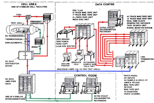
Schematic: Transient Performance Measurement (1981)
© Procurement Executive, Ministry Of Defence
A second monitoring and data recording system was also used, this being the transient performance measuring system.
|
|
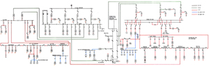
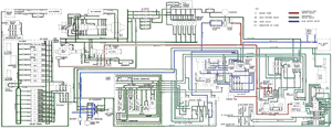
Schematic: Electrical Power Supplies (1981)
© Procurement Executive, Ministry Of Defence
Pyestock was a huge consumer of electrical power. Not only did it have its own
Power Station, but it required several separate incoming feeds, which
were stepped down in various transformer parks at either end of the site, before being distributed at various voltages.
This schematic shows all these various ring mains, and the switching available between each.
|
|
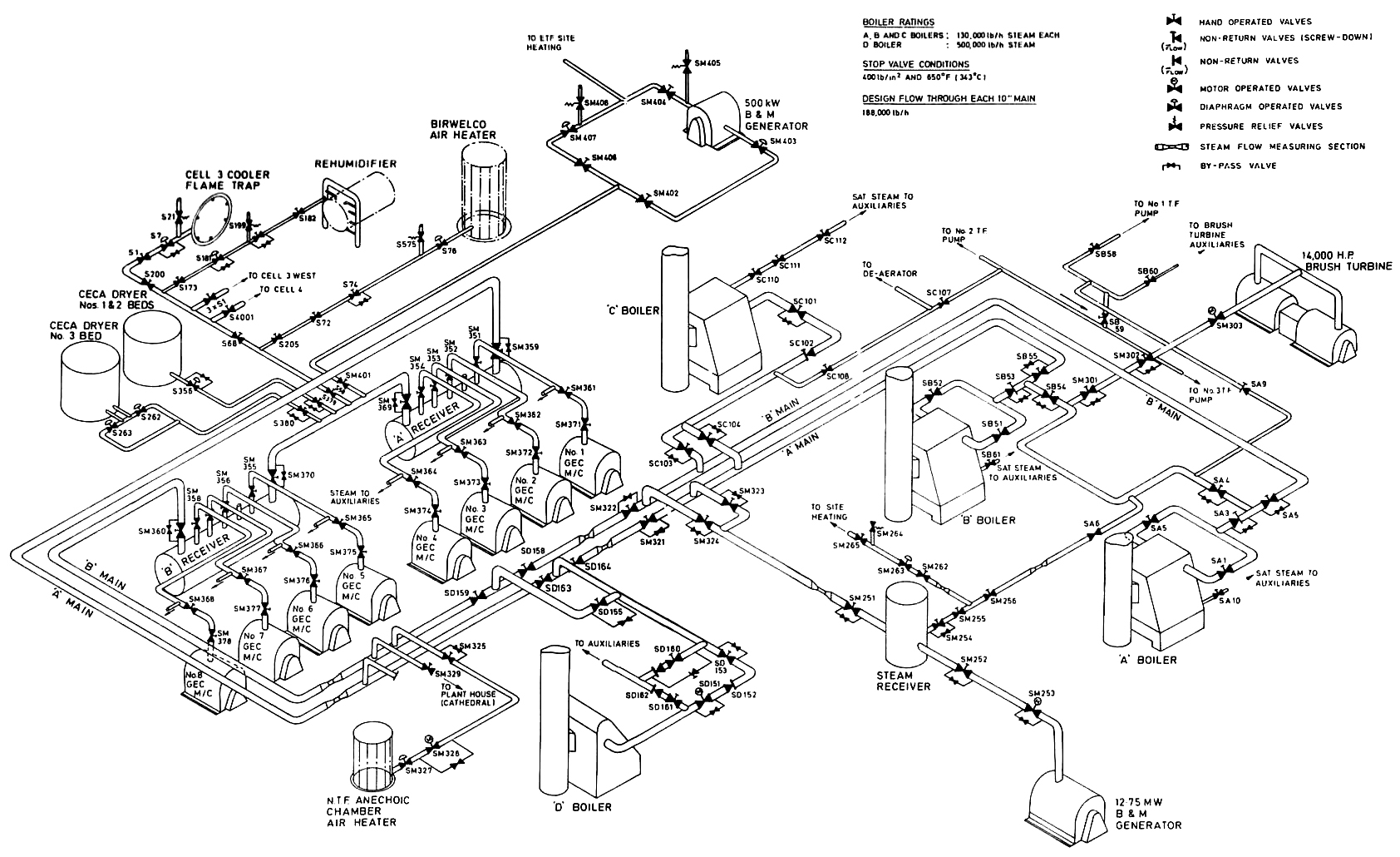
Schematic: High Pressure Steam Distribution System (1981)
© Procurement Executive, Ministry Of Defence
Whilst Pyestock was dependant on electrical supplies, it was also dependant on steam for several
different functions e.g. starting the GEC compressor/exhauster sets; running various turbines; driving the
generators in the Power Station and supplying heat to the entire site.
This diagram shows how the Battle Test House boilers, along with 'D' boiler
(which used to stand near the Air House Cooling Towers), were interconnected to provide all these functions.
|
|
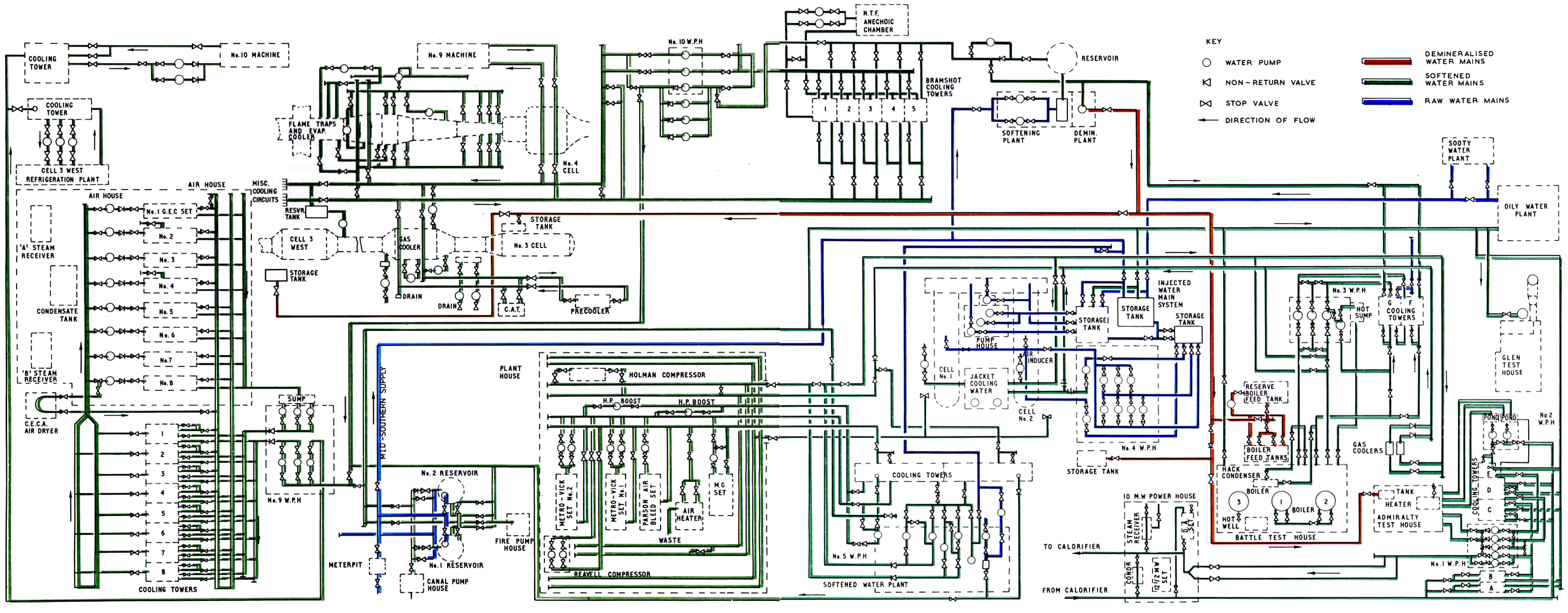
Schematic: Water Supply Circuits (1981)
© Procurement Executive, Ministry Of Defence
Water was a vital coolant for many of the test cells. Additionally it was often frozen and injected into various test
cells for icing and wet tests.
As this diagram shows, the cooling system at Pyestock was extremely extensive, and not simply a matter
of a circulating flow between a test cell, its cooling tower and an associated pump house.
|

|
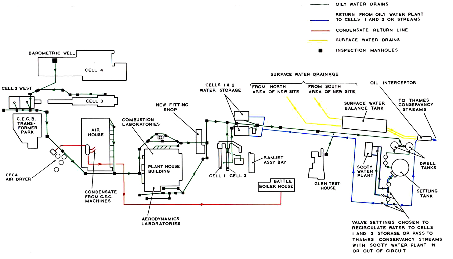
Schematic: Test Cell Drainage System (1981)
© Procurement Executive, Ministry Of Defence
Whilst water was circulated around the site, waste was collected in various barometric wells and storage tanks
before being pumped to the sooty water plant where it was processed and cleaned.
This diagram shows the wells, drains and pipes required to collect the waste and send it for processing.
|
|
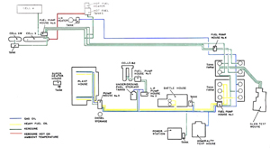
Schematic: Fuel Distribution System (1981)
© Procurement Executive, Ministry Of Defence
It’s easy to forget that the various engines being tested required a fuel supply. Pyestock was equipped with
a tank farm (to the east of the site) which stored gas oil, heavy fuel oil, kerosine and hot kerosine.
From the tank farm, it was pumped by a series of Fuel Pumping Houses to each of the individual cells where it
was then fed to the engines.
|
