|
History
home | history | the air house (a view from the floor)
The Air House (A view from the floor)
|
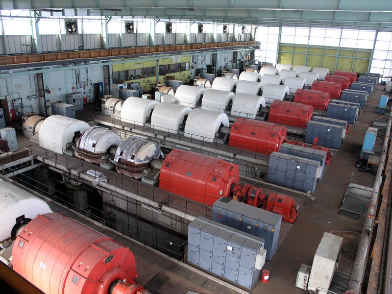
When I first entered the Air House, it was really quite scary, it is difficult to convey the scale of the machinery inside and even
those of you who have "explored" and seen these beasts at idle will have no idea of the noise, heat and vibration that filled the
entire building when they were running at full power. I was employed by the MOD as an "Experimental Worker – Grade 3" (EW3) and
I was part of a two-shift crew who ran and maintained the Air House,
the Plant House,
Number 9 Exhauster and
Number 10 Exhauster.
(Scientific Officers and Engineers will tell you they ran the machines but they stayed tucked-up in air-conditioned and sound-proofed
control rooms while we and the fitters were down in the bowels of these behemoths while they hungrily consumed their 27Mw each!).
|
I'll concentrate on the Air House as this is by far the most used (and now most photographed) part of Pyestock.
|
Sunset through the Air House. Eastern side of the
building.
31|03|07 © Simon Cornwell 2007
|
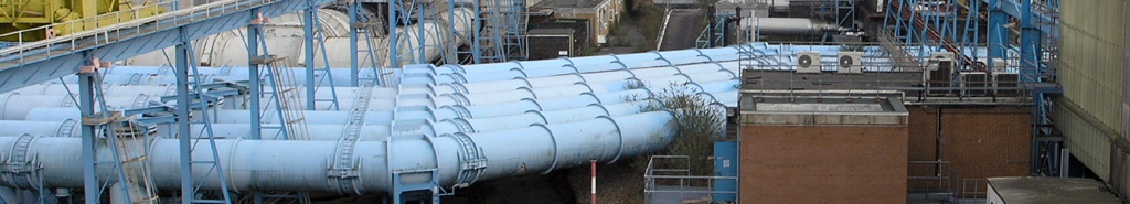
The eight compressor/exhauster sets you see in photographs were fairly simple to run as most of the control
systems were automatic and we only had to regularly patrol all three floors of each machine whilst in use (a very hot and noisy job)
looking and feeling for problems (yes, feeling as the noise levels were so high any unusual noise you could hear would indicate
cataclysmic failure somewhere!). On the other hand, starting the sets was a time consuming, complex and physically demanding job – please
remember that at the time I was there the steam turbines were still in use. When asked to start one (or sometimes two) machines the process
went something like this:-
- Start the ‘flushing’ oil pumps to send oil to the massive bearings
- Start the ‘jacking’ oil pumps to lift the shaft (60+ tons!) clear of it’s white metal bearings
- Engage and start the ‘barring’ motor at the far end beyond the main electric motor to start the whole shaft rotating at about 5 rpm
- Unlock and open main steam isolator valve
- Open the steam manifold
- Open the valve to release steam to the desuperheater
- Open the valve to release steam to the ejectors to start decompressing the condenser
- Go down to ground level, close all the air main drains
- Open the water pump bypass valve
- Return to machine floor
- Start the water pump and open delivery valve (via remote switch) until pump drawing 380 amps
- Closely monitor steam pressure and temperature
- When condenser vacuum reaches 20” open valve to start steam turbo oil pump (mounted just under machine floor on top of main oil tank, make sure ‘flushing’ pump switches off
- Closely monitor steam pressure and temperature, steam temperature should be approaching 270c
- When condenser vacuum reaches 22” crack open main steam throttle valve to start the shaft rotating under turbine power, check when rolling that the ‘barring’ motor has disengaged
- Adjust throttle valve to take shaft speed up to 1250 rpm
- Hold shaft speed until steam temperature has exceeded 273c (so there can be no water droplets which would damage the turbine blades)
- If the steam temperature does not rise sufficiently (mostly when only one or two machines in use, remembering that the steam came from nearly half a mile away) then have the air inlet bleed valves opened to apply load to the compressors so throttle valve has to be opened more drawing more steam through the system
- Hold machine at 1250 rpm until signal to raise speed received (signal is series of lights on annunciator panel as verbal communication not possible due to noise level) this period could be anywhere between 5 minutes and an hour.
- When requested open throttle valve to bring shaft speed up to 3000 rpm (pass 1700-2500 quickly as harmonic vibrations are generated which are ‘uncomfortable’)
- When speed stabilised at 3000 rpm notify control room who will take over throttle control and at exactly 3000 rpm engage main motor. (Explorers who have been in the control room will have noted ‘pull-out’ sections in the middle of the main control panel. This is the synchronising panel used to indicate the shaft speed relevant to grid frequency so the two can be matched making the transition from steam to electric power seamless (who wants to jolt a 60 ton shaft running at 3000 rpm?))
- Whilst you are doing all this, don’t forget you have to do the same to the machine next door at the same time! (Explorers will note that the stairs between each floor are ‘paired’ for this reason)
|
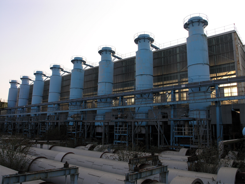
The eight compressor/exhauster sets looking north.
03|03|07 © Simon Cornwell 2007
|
The control room now has control of the machine and task now reduces to walk-round inspections
and recording of relevant temperatures and pressures.
Shutting down is a simplified reversal of this process but from when the power and steam are cut, the shaft will
take up to 17 minutes to stop rolling. Once the shaft has stopped, the ‘flushing’ and ‘jacking’ pumps are restarted
and the shaft is left to rotate for at least 1½ hours whilst it cools and then the ‘flushing’ oil pump runs for
a further 10 hours whilst the bearings cool.
Of course all of this was made redundant after I left as the technology was finally available to start the machines
on the electric motor alone using variable frequency starting, but it couldn’t have been the same with no brass dials
and gauges to polish, the smell of burning oil or first degree burns caused by steam leaks!
Ric Canham AMIMI
|