New
Introduction
Virtual Tour
The Buildings
History
Documentation
About
Links
Urban Exploration
Pyestock Diaries
Academia
Media

The Buildings

home | the buildings | cell 3 west (649) | chris' diagrams


The following diagrams of Cell 3 West were designed by Pyestock employee Chris Jarvis.


© Chris Jarvis


© Chris Jarvis

"I have sent you two sketches one with the Cell 3 West set up in running mode (above and with the the Dry Air Animation above) and the other with the End Dome open on its tracks (below). The air was sucked into the throat of the engine on test." - Chris


© Chris Jarvis

"The engine was mounted in the Thrust frame to measure thrust (see the Thrust Frame Animation below)" - Chris


© Chris Jarvis

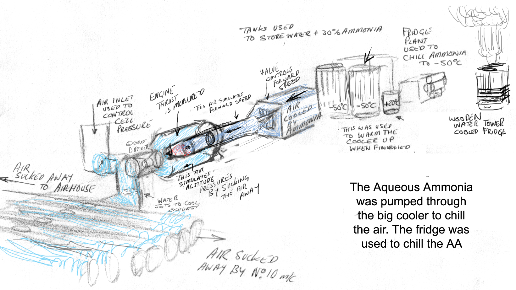
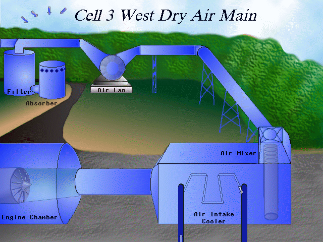
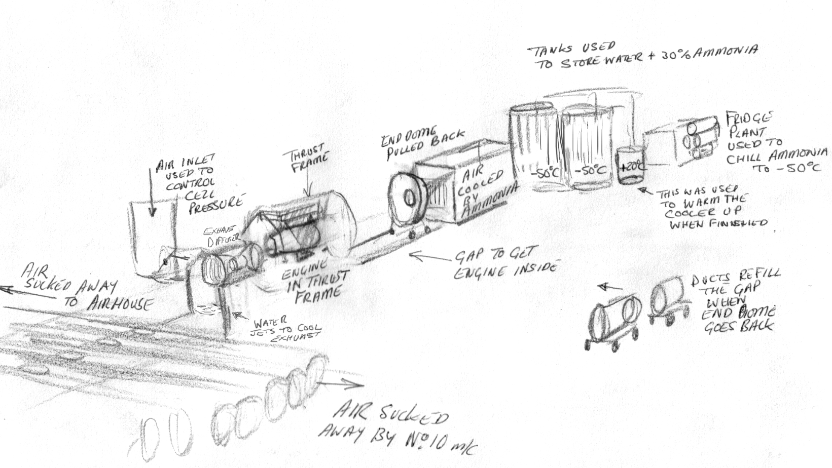
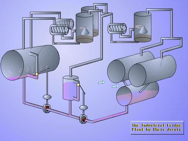
"The incoming air was chilled using water mixed with ammonia (antifreeze). The water/ammona was refridgerated by the fridge plant (see the Fridge Animation below) The plant was cooled with water from water tower (see the Fridge Animation below)."

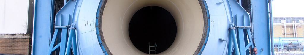
"The Cell was vacummed to simulate altitude. The altitude was controlled using an inlet valve at the exhaust end (the more you closed it the higher your altitiude). The forward speed was controlled using a louver valve in the intake cooler" - Chris


© Chris Jarvis

"The amazing thing about Cell 3 West was that it sucked air through a hole the size of a house and yet maintained a vacuum in the chamber to simulate 30,000 feet or even higher at times. There is a cold plant which also chilled two huge tanks of ammonia which was pumped through tubes to chill the air to -30°C. This was measure the amount of thrust generated at high altitudes and cold temperatures (The thinner the air the lower the thrust, like rowing a boat with your oars out of the water)" - Chris