 | The Noise Test Facility |
44. Noise testing
Research into the problems associated with aircraft noise has continued at N.G.T.E. for several
years and the first anechoic testing chamber employed for this purpose was built in the early sixties; this test
equipment is described in Section 5, Paragraph 32. The increasing demand for quieter aircraft which has arisen in
recent years has further stimulated the demand for more research work in the noise field with the result that it
was decided in 1969/70 to build a larger test facility capable for undertaking large scale noise tests on a variety
of gas turbine components and associated equipment.
The new Noise Test Facility will complement existing facilities in the UK for experimental work
on aero engine noise porblems by providing for the testing, at relatively large scale, compressors, turbines, jets
and ducts having absorbent liners. It is envisaged that the equipment will be used for a wide-ranging variety
of research and development programmes by both government workers and industry.
The facility has two main laboratories and the predominate feature of the construction is that
the two units have been built quite separately on two different sites. These units are: -
- The Absorber Rig Facility
- The Anechoic Chamber Facility
The Absorber Rig Facility was the first to be completed and it came into service in the summer of 1972. The Anechoic Chamber
Facility was commissioned just over one year later in early 1974.
45. The Absorber Rig Facility
The Absorber Rig Facility consists of a reinforced concrete structure capable of containing all internally
generated noise and of reducing noise interference from external sources to a minimum.
There are four main parts to the building, the heart of which is the working section; additionally there
is an air supply with upstream and downstream silencing splitters, a control room and exhaust silencing splitter block.
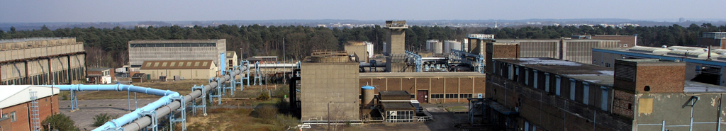
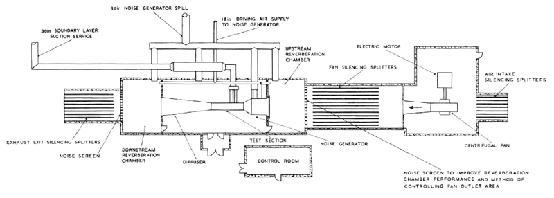
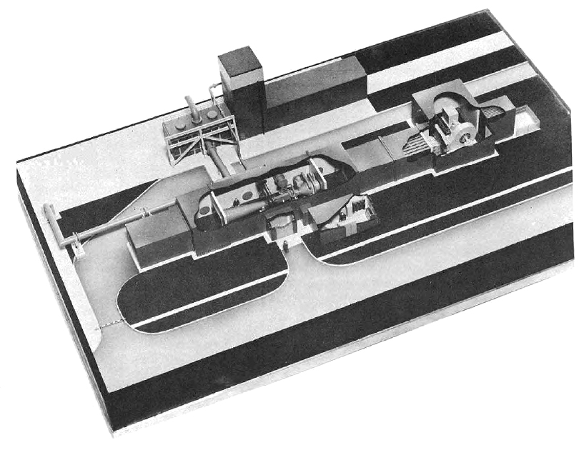
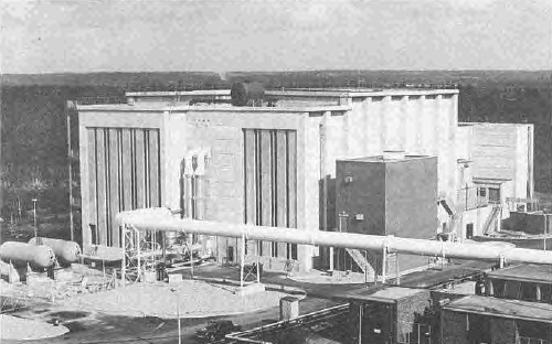
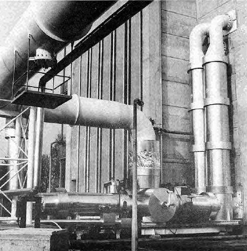
The facility is shown in cross section in Figure 135 whilst Figure 134 shows the plant externally with the exhaust exit
splitters in the centre left forground.
|
|
Fig. 134. A General View of the N.G.T.E. Noise Test Facility Absorber Rig.
|
|
|
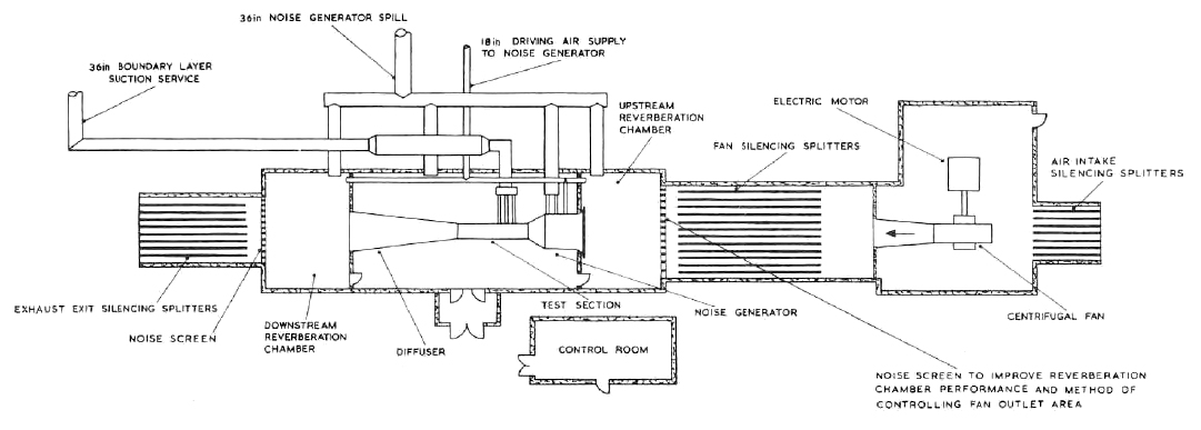
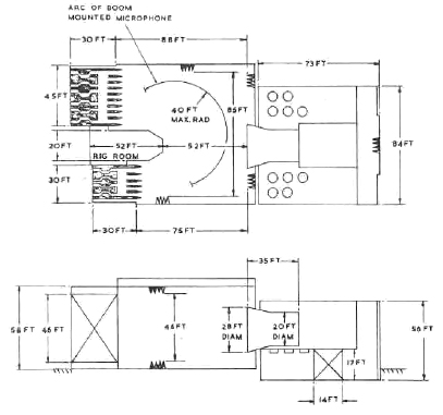
Fig. 135. Plan Layout of N.G.T.E. Noise Test Facility Absorber Rig
|
The working section itself consists of three closely related components, namely, the test section
and the Upstream and Downstream Reverberation Chambers. Thesting of acoustically absorbent ducts is conventionally
done by mounting the duct in the test section, generating sound artificially in one reverberation chamber and observing
how much appears at the other. The hall which accommodates the working section is 50ft by 20ft by 16ft high and is
situated between the two reverberation chambers both of which are 14ft long by 20ft wide by 16ft high; communication
operings 8ft 6in square permit the connecting of the test apparatus to the reverberation chambers. The overall layout of
the Absorber Rig Facility is shown in Figures 134 and 135. These diagrams show nthe location and layout of the test
section and its position between the two reverberation chambers which are physically separated from test section
at all points with rubber strip filling sandwiched between concrete beams and rafts; this construction minimises any
earth transmitted vibrations which could adversely affect the purity of generated noise. All walls are 12 inch thick
reinforced concrete and the floor of the test section has built-in 10in by 10in I beams to act as bedplates on which
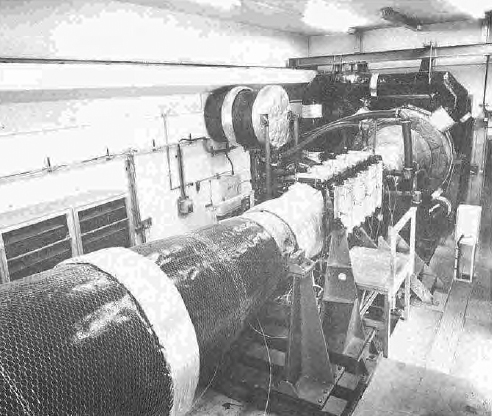
test ducting and other apparatus can be mounted and a 3-ton overhead travelling crane is also available. Figure 137
illustrates the general details of the working section and Figure 138 the section which houses sample sound absorbent
liners on test.
|
|
Fig. 136. Sectional arrangement showing N.G.T.E. Noise Test Facility Absorber Rig.
|
|
|
Fig. 137. General View of Noise Test Facility Absorber Rig
|
|
|
Fig. 138. Noise Test Facility Abosrber Rig Test Section.
|
The upstream and downstream reverberation chambers are relatively open areas although all surfaces have
a grid pattern of anchorage points which can be used for securing microphone support structures and similar noise research
devices.
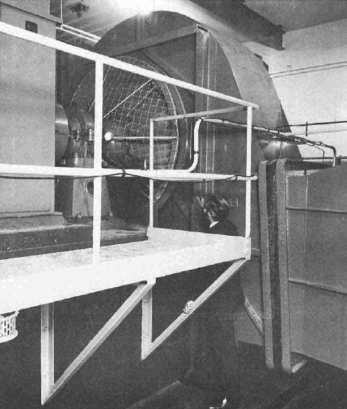
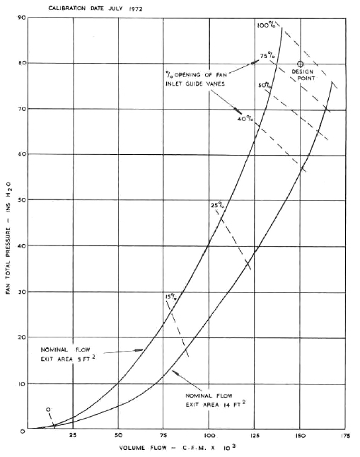
Air is blown through the test section by a centrifugal fan; manufacturered by Davidson & Co. Ltd., this
unit has a double entry impeller 86½ in diameter and its output is controlled by rotating vanes set in the
eye of the impeller and which are operated by pneumatic actuators. The fan is rated at 150,000 scfm (i.e. about 190 lb/s)
at a head of 80in water guage; the fan is sited upstream of the working section as shown in Figure 135; the general view
of the fan assembly is shown in Figure 139, whilst Figure 140 provides the fan characteristic. The fan is driven by 2250 horsepower
induction motor having a rotational speed of 1485 rev/min; the electrical supply is 11 kilovolt, 50 cycles, 3 phase. This
air supply is sufficient to give a Mach number of 0.7 in a test duct of 4 sq ft cross sectional area, while a diffuser
downstream of the test sections recovers sufficient velocity head to achieve the design Mach number with the available
fan pressure rise. The fan room is provided with splitter silencers at entry, to control external noise emission, and
at exit, to prevent fan noise from interfering with acoustic measurements in the upstream reverberation chamber.
|
|
Fig. 139. General View of Noise Test Facility Absorber Rig Fan Room.
|
|
|
Fig. 140. Performance of Noise Test Facility Absorber Rig Fan
|
Adjustable plates forming noise screens are fitted at the interface between the upstream reverberation
chamber and the fan outlet splitters and between the downstream reverberation chamber and the exhaust exit splitters. The screens
increase the reflection of noise within the reverberation chambers and the former also provides a method for varying the
fan outlet area and hence the resistance to fan output.
A pressure or suction air service is installed and this is supplied from the
Plant House MV compressor/exahuser plant described in Section 1, Paragraph 8
by way of a 36in diameter supply line that is connected to the main ring main near the
Battle Boiler House. The air supply of 60 lb/s at 5.5:1 pressure ratio is
available in the Test Hall and both reverberation chambers; mainly the pressure/suction service is required for driving
a noise generator and to enable the boundary layer developed in the working section (approximately 10 lb/s) to be pumped
away thus providing boundary layer control. An extra connection adjacent to the test rig allows the noise generator driving
air to be ducted away independently of the rig flow thereby minimizing interference with the main rig flow.
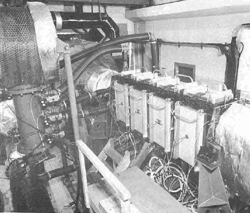
Noise research programmes in the aero engine field make it desirable to reproduce octave band sound
pressure levels up to 160 dB in the test section but, since it would require impractically large qunatites of sound
to be generated in the large reverberation chambers, the high levels will be produced by mounting the noise source
in a 5ft 6in diameter section of the ducting upstream or downstream of the test section. The facility has a noise
generator designed to produce 35 kW of sound power, it comprises a cluster of up to 32 Hartmann generators arranged in an
annular cavity around the 5ft 6in duct; Figure 135 shows the noise generator sited in the upstream position. Acoustical
tuning of the noise generator output is achieved by altering the number of individual generators, their size and/or
the arrangement of the generators within the cluster.
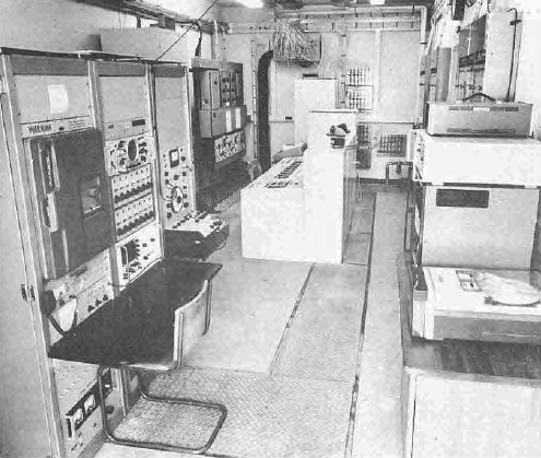
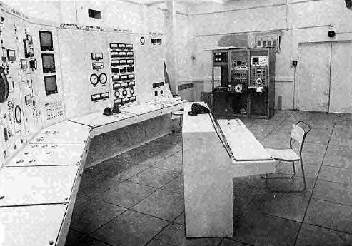
The control room which is sited adjacent to the test chamber is located where shown in Figure 135,
the general arrangement is shown in Figure 141. In the control room driving instruments, fan controls and
value controls for service air are all located on the single unit control desk. Adjacent to the control desk
a 100-channel Solartron Compact 33 data acquisition system enables facility and rig parameters to be continuously
monitored.
|
|
Fig. 141. Noise Test Facility Absorber Rig Control Room
|
The separate acoustic console, left foreground in Figure 141, contains an Ampex 14-track magnetic
tape recorder, a frequency analyser and level recorder unit and a twin-beam oscilloscope for visual display of the incoming
and recorded microphone signals.
On-line anaylsis can be completed using the General Radio third octave analyser described in
Paragraph 47.
46. The Anechoic Chamber Facility
The construction of the N.G.T.E. Anechoic Facility makes available a 10,000 cubic meter
nominal capacity chamber for noise testing, in which the enclosed working volume has nearly zero noise reflection,
thereby reproducing environmental conditions which, except for the effects of forward speed, can be compared
to those in flight where there are no cloud or ground effects. The Anechoic Test Chamber
therefore, provides conditions opposite to those in the Absorber Facility, and permits the research working to separately
indentify the source and direction of noise wave phenomena. The building is principally indended for the noise testing
of jets, turbines and certain configurations of acoustically lined ducts over a frequency range of 100 to 20,000 Hz
and source noise levels up to 170dB overall PWL (ref 10-12 Watts) can be operated in the chamber within the
community criterion. The plant incorporates an engine or rig room fitted with bedplate and dynamometer for the
installation of engines, turbines and/or test ductwork which can simulate flight exhaust systems.
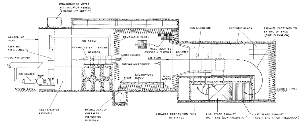
Broadly, the facility consists of an acoustically lined main test chamber 85ft wide and 46ft high
with an overall length of 88ft, but which is reduced to 52ft at the working section. The jet flow from the main noise
source is projected towards an acoustically lined, flared duct 28ft diameter at inlet with a 20ft diameter throat, which
acts as an exhaust inducer.
The low noise reflection characteristics of the main Anechoic Chamber is achieved through lining the
walls with sound absorbing wedges having sound pressure reflection coefficients of less than 10% over the design range
of frequencies. Jets discharged from nozzles generally entrain a large quantity of air and to balance the inducer effect
from the engine rig noise noise and restore near atmospheric pressure in the main chamber, two large splitter assemblies
are available at the front end of the building to let in a stream of induced air which mixes with the noise jet stream
as they both pass through the exhaust inducer duct.
Downstream of the exhaust duct there is an independently constructed substantial concrete structure
which houses the Anechoic Chamber exhaust system. The design allows the mixed exhaust air flow to be pumped back
to atmosphere using ten large extractor fans having a total capacity of 1600 lb/s which is sufficient to ensure correct
mixing of, for example, jets of 18in diameter blown up to the choking pressure ratio. The general arrangement of the
exhaust system structure allows the air stream to be separated and diverted before it passes through a two stage splitter
system on the way to the exahust fan inlets; in this manner the exahust stream flowpath completely reverses its direction
before it is pumped out of the building in a vertical direction. The whole exhaust structure is fitted with acoustic
linings which together with the splitter systems, silenced fans and independent construction prevent the ingress
of extraneous sounds to the Anechoic Chamber from the extractor fans and/or other external sources.
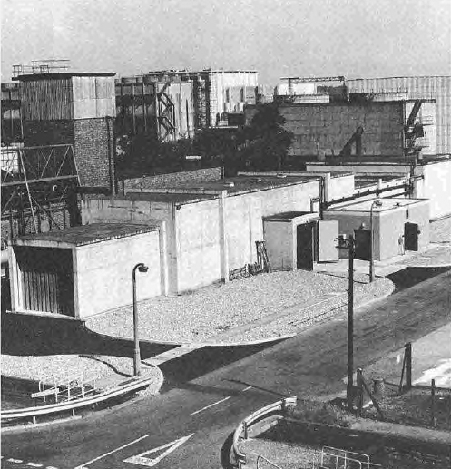
An external view of the Anechoic Facility looking in the North-Easterly direction is shown on Figure 142.
This picture shows the induced air inlet splitters at the front end of the building with the GEC air supply pipework
and air heater unit in the foreground. The exhaust system structure can be seen in the background with the control
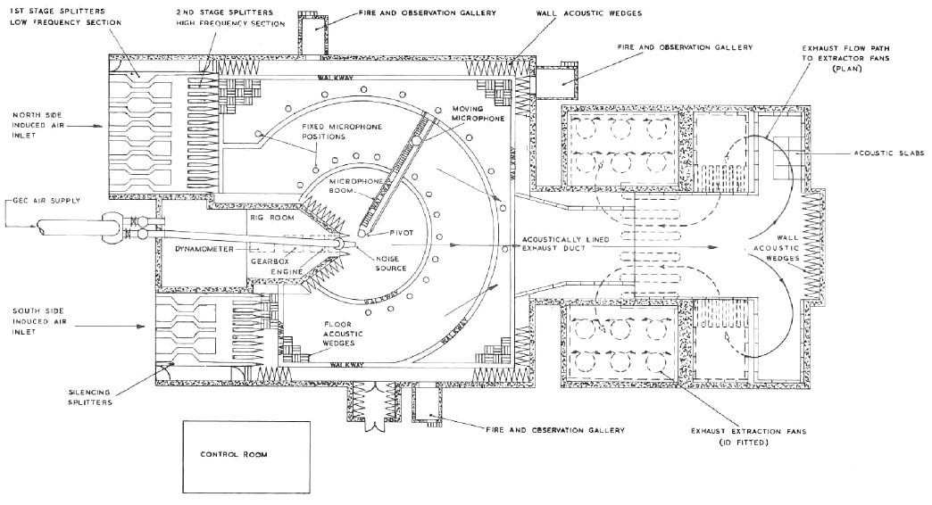
building on the righthand side of the picture. Figure 143 and 144 show side elevation and plan cross sections of the
facility, and an idea of the exhaust flow pattern can be obtained from these diagrams. Figure 145 gives an overall
view of the Anechoic Facility and Figure 146 shows the Anechoic Test Facility leading dimensions.
|
|
Fig. 142. General External View of Noise Test Anechoic Facility looking in North-East direction.
|

|
|
Fig. 143. Noise Test Anechoic Facility Side Elevation
|

|
|
Fig. 144. Plan View of Noise Test Anechoic Facility
|

|
|
Fig. 145. Sectional Arrangement of Noise Test Anechoic Facility
|
|
|
Fig. 146. Leading dimensions of Noise Test Anechoic Facility
|
The most striking feature of the Anechoic Chamber itself is the sound reflecting wedges of which
there are nearly 7,000 units covering the walls, ceiling and floor. Three indiviudal wedges are mounted together on a base-frame
to form each single unit 610mm square; these units are then arranged over the chamber surfaces so that each successive unit
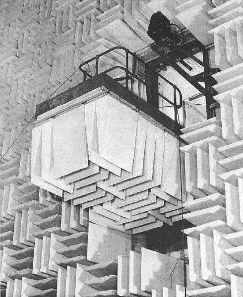
has its wedge peak edges at right angles to the neighbouring unit. The wedge assembly details are shwn pictorially in Figure 147
which also shows a close-up view of one of the retractable observation galleries when the gallery is in the 'down position.'
|
Fig. 147. Retractable observation gallery showing details
of Wedge
Assembly Noise Test Anechoic Facility.
|
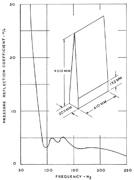
The wedges are manufactured from bonded glass fibre slabs 51mm thick, and 610mm wide, having a density of
36 kg/cu m and a fibre thread diameter of 6.5 micros. The manufacturers quoted specific flow resistance from
tests being 7.5 x 10² mks Rayls/m. The slabs are mounted in pairs and cut slantwise through their thickness
and then assembled back to back to form tapered wedge elements, 203mm thick by 610mm wide. The overall height of the wedge
element is 900mm, of which the rectangular base contributes 152mm and the triangular section 748mm. Each glass fibre
wedge element is covered in a scrim cloth cover and three wedge elements put together and reinforces with a coarse mesh
wire cage form the complete unit that is fitted to the Anechoic Chamber walls.
The wedges are mounted from the chamber walls by horizontal sheet metal channel supports fitted on
wooden batterns; the arrangement gives a nominal air gas between the wall and fibre wedge of 120mm and an overall depth
of acoustic treatment, wall to wedge tip of 1,020mm. A strip of glass fibre blanket 150mm wide x 25mm thick is packed between
all wedge units to further improve the acoustic performance.
The acoustic performance of the wedge material has been measured experimentally using an impedance tube
and the resulting characteristic is shown in Figure 148, which shows the sound absorption coefficient of the
wedge is 0.99 and the cut-off frequency is less than 100Hz.
|
|
Fig. 148. Acoustic performance characteristic of Sound reflection wedges
in the Noise Test Facility Anechoic Chamber.
|
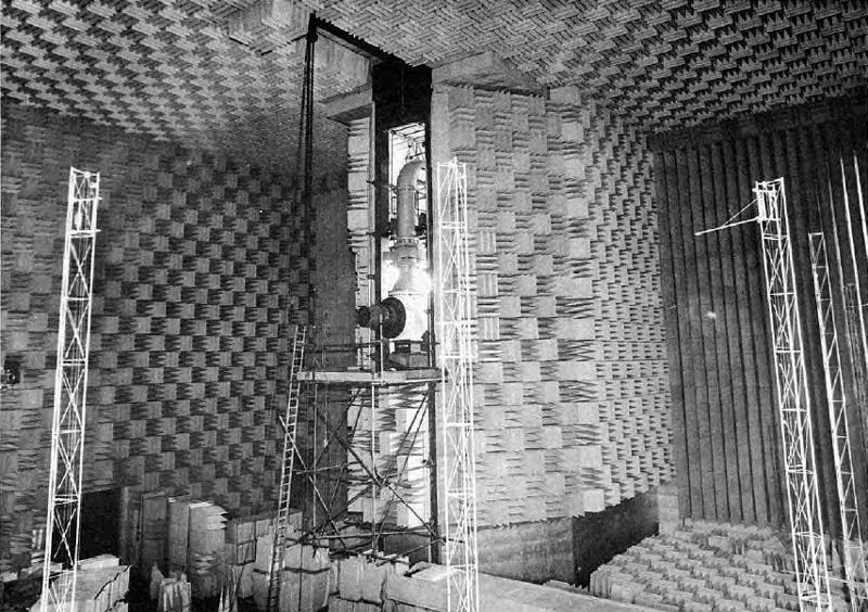
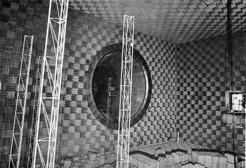
General views of the Anechoic Chamber are shown in Figures 149 and 150, the former lookings upstream
to the induced air splitter assembly on the northern flank, and the latter downstream towards the 20ft diameter
exhaust collector.
|
|
Fig. 149. The Noise Test Anechoic Chamber looking upstream, showing the North Side inlet splitter.
|
|
|
Fig. 150. The Noise Test Anechoic Chamber looking downstream towards the exhaust collector
inlet with the microphone masts in the foreground.
|
The construction of the north and south inlet splitter assemblies follow the normal design practice
which has been used on other N.G.T.E. test beds for a number of years; sound absorbent filling made of
incombustible spun mineral fibre covered by scrim cloth, is held in galvanised perforated mild steel sheet cases
22 swg. thick and mounted on timber frames. The thoughway area between the splitter segments of the combined north and
south assemblies is 920 ft2 through the front low frequency section, and 875 ft2 through the tail
end high frequency section; the length of the splitters is 25ft, made up of 18ft low frequency and 7ft high frequency
sections, there is a 6ft gap between the two sections, thus the overall length of the splitter units is 31ft. The splitter
height is 46ft.
Methods of mounting microphonic equipment are built into the Anechoic Chamber design and an indication
of the arrangements is given in Figure 144, and the pylon mountings are seen in Figures 145, 149 and 150. Fixed
microphone stations are built into the Chamber floor at 15° intervals both on arcs of 20ft and 40ft radii with
narrow walkways through the floor wedge assembly. In addition, a pivoted electrically operated boom whose height is
set to clear the top of the floor wedges, allows angular microphone traverses to be made. A mast carrying the microphone
equipment can be fixed to any radius along the 40ft span of the boom which can traverse through 90° from the chamber
fore/aft centre line position towards the south side inlet splitters and approximately 130° towards the north side
splitters, i.e. 220° in all. By remote electrical control, the boom can be made to swing in an arc at infinitely
variable rotation speeds, between the limits of 0.25°/s and 2°/s. Pylon masts are used both on the boom and
at the fixed stations to raise the microphones up to the level of the noise source. If and when necessary, the boom can
be used as a mechanical handling device to transfer engineering stores from the south entrance doorway porch, over
the floor wedges, to other parts of the chamber.
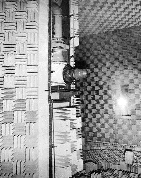
A monorail lifting beam capable of carrying tackle which can lift three tons is fixed to the Anechoic
Chamber ceiling at the centre line in a fore/aft position which most usefully helps personnel working on the noise source
nozzle assembly, see Figure 151 which shows a typical noise source nozzle assembly in position with some of the wall mounted
wedges removed to assist installation. The overhead lifting beam, fixed position microphone masts and associated floor
walkways are also visible in the photograph.
|
|
Fig. 151. Typical noise source nozzle assembly.
|
The main features of the exhaust silencing structure are the exhaust collector, the acoustically
slabbed walls of the concrete ducts which reverse the flowpath, two sets of silencing exit splitters, high and low
frequency, and the ten exhaust extraction fans. All these items may be identified from Figures 143 and 144.
The structure itself is built in reinforced concrete and like the main Anechoic Chamber has 14in thick
walls to resist the import of external noise. The internal walls are lined throughout with acoustic facings which
vary between 6 and 20in thick according to location. This acoustic treatment consists of at least 4in of rockwool packed
at 9 lb/ft3 with 2in thick RB4 Lantor faced slabs on the face, there is a 16in gap between this acoustic treatment
and the reinforced concrete wall. Wedges replace this acoustic treatment at that part of the back wall which is directly
facing the exhaust flow.
The exhaust collector is acoustically treated around its periphery, this lagging consists of heavy
density rockwool 8in thick, faced with cotton sheeting and perforated galvanised mild steel sheet. The duct itself is
prefabricated from 0.25in thick steel plate and has a total length of 35ft.
The exhaust flowpath at first bifurcates before passing through dual first stage high frequency
splitters having a combined total throughway area of 306ft2 and a length of 8ft. Afterwards, the
two exhaust streams combine and pass through a second stage low frequency splitter assembly with a throughway
area of 340ft2 and also a length of 8ft; this second set of splitters is at right angles to the
first stage assemblies. The first stage splitters are filled with rockwool at 6.0lb/ft3 and
the second stage at 9.0lb/ft3.
On leaving the second stage splitters, the mixed exhaust airstream splits again to enter
two similar fan inlet chambers, one on the north side and the other on the south side of the structure;
the exhaust fans are mounted in the roofs of these two chambers to exahust vertically to atmosphere.
Each fan chamber is constructed with the concrete moulded, so that six similar fans can be installed.
At present, there is one vacant position on each chamber so that ten fans are installed, five per chamber.
It is important that the flow pattern in the exhaust system is evenly distributed so that each fan unit
consumes approximately the same amount of electric current and when the plant was commissioned particular
efforts were made to balance the airflow distribution pattern.
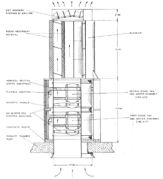
The fan units themselves are 75 J½, 956 rev/min, 24° to 25° double axial units
having two coutner-rotating six bladed fans in each pod, both with its own electric motor. The pod units are
fitted with inlet bell mouths, modified 'C' type silencers and discharge shutters and are made by Woods Ltd.
of Colchester, a part of the General Electric Company. The pod units are 75in diameter and 22.5ft long overall.
Each of the fans in the pod is driven by a 440V, 3 phase, 50Hz, 130hp weatherproof, electric induction
motor which is continuously rated for maximum specified duty. Each fan pod therefore consumes at
maximum output the electric current equivalent of 260 horsepower, although the first and second stage
fan units can be switched on together or used singly with a corresponding drop in current consumption
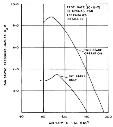
and output. The nominal output of each fan unit is 1.44 x 10⁵ cfm at 6.0 in water gauge, although
at maximum flow the head falls to 0.8 in water gauge; the output characteristic for one fan assembly is
given in Figure 152 for both single and dual fan operation.
|
|
Fig. 152. Output performance characteristics of a single 75 J½ exhaust
extraction fan assembly for the Noise Test Facility Anechoic Chamber.
|
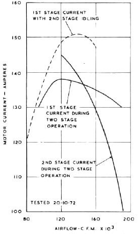
The characteristic shows that the actual experimental output is better than the nominal
design flow. Figure 153 shows the electric power consumption of the fan motors. The total flow capacity
of ten fans together is 1.44 x 10⁶ cfm. As the fan unit design permits single or double fan
impeller operation, the research staff are able to control the output capacity of the system either
by selecting the number of fans uses in any test, or by halving the fan unit throughput by operating
with the first stage alone, together the two methods provide a 20:1 turndown capability. Figure 154
shows a cross-section of one of the fan pod assemblies.
|
|
Fig. 153. Electrical power consumption of fan motor Noise Test Facility
Anechoic Chamber.
|
|
|
Fig. 154. Exhaust fan motor assembly Noise Test Facility Anechoic Chamber.
|
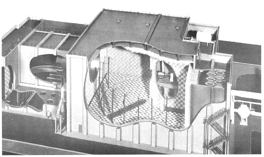
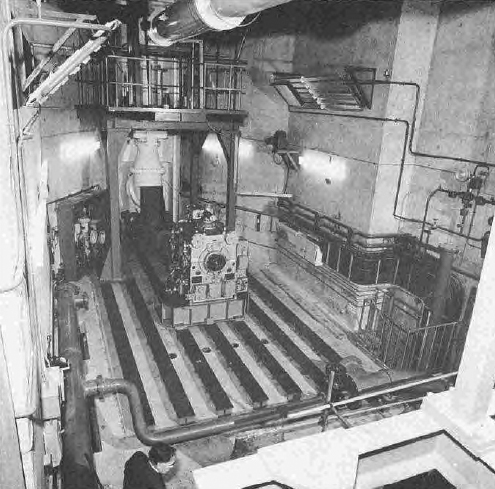
The rig room is about 50ft long by 20ft wide decreasing sharply to about 5ft at the
discharge end. The main arrangement and dimensional layout are shown in Figures 146 and 155, the latter
gives a pictorial illustration of typical rig ductwork and nozzle assembly. The rig nozzle centre is
located on the vertical centre line of the Anechoic Chamber when the rig is installed 5ft above the level
of the floor bedplate, to make this possible the rig room floor level is elevated above ground level
and the bedplate is mounted on a massive reinforced concrete structure.
|
|
Fig. 155. Noise Test Facility Anechoic Chamber Test Rig Room.
|
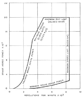
When appropiate, a 20,000 hp 2940/8500 rev/min dynamometer, Heenan and Froude Ltd.
type DA 790, which can be coupled to a 2:1 double train epicyclic gearbox made by Vickers - Crown Orbital
Gears Ltd., is available to absorb power generated in any test rig which features an engine turbine
assembly. The performance characteristic of this dynamometer is shown in Figure 156; by using a 2:1 step-down
gearbox, turbines of 5880/17000 rev/min speed range can be installed and operated.
|
|
Fig. 156. Performance of DA 790 Hydraulic Dynamometer Noise Test Facility
Anechoic Chamber Rig Room.
|
The test cubicle is provided with a closed circuit water cooling system supplied from
the 'Bramshot' cooling towers described in Paragraph 41; the system which has a maximum throughput of
2,900 gals/min at 182ft head is shown diagrammatically in Figure 157. Two Sigmund Pulsometer Ltd. pumps
type HSC 8/10Y are used to supply the water, and there is a sump tank fitted with two Sigmund Pulsometer
submerged scavenge pumps in the return circuit to the cooling towers. Although the water cooling system
has a general application, it was particularly designed to provide the service to the type DA 790
dynamometer and it therefore includes a 3150 gallon capacity pressurised accumulator stroage tank on the
Anechoic Chamber roof which is used as an emergency water supply to permit the test rig to be shut down
in the event of a failure of the pumped water supply. The accumulator is air pressurised to provide a
head of 55 p.s.i.g. The rig room is also provided with the normal compressed air and other general
ring main services necessary for satisfactory test rig operation.

|
|
Fig. 157. Cooling Water Circuits for Noise Test Facility Anechoic Chamber.
|
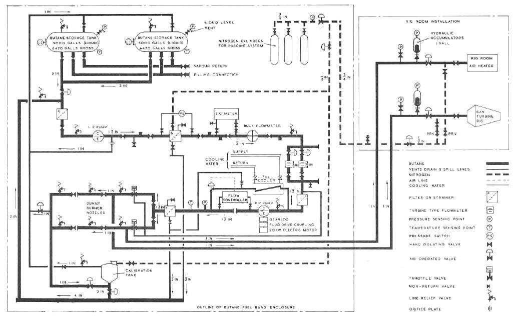
A fuel system using liquid butane is avaialble for tests with combustion systems and
turbines representative of engine conditions. The particular use of butane oil instead of kerosine, avoids
the risk of unvaporised liquid fuel contaminating the highly absorbent wedge units and other lagging materials,
which could produce in due course circumstances that would constitute a highly dangerous hazard; butane
fuel on the other hand, readily vaporises if spilt within the confines of the Anechoic Chamber. To
pump butane, a special fuel pump is supplied as a part of the fuel system, the pump is a Sundune model
BMP 311, capable of supply 31.3 gallons/min at 4428 ft head; the unit is driven by a 90 kW 145 amp
motor through a Fluid Drive variable speed unit and 200 hp increasing speed gearbox of 2960/23,
700 rev/min ratio. Butane is stored in two storage tanks, nominally of 5000 gallons capacity, sited at the
front end of the Anechoic Chamber building; the fuel system incorporates built-in flow measurement,
regulators and the usual valve controls. Figure 158 shows a diagrammatic arrangement of the butane
fuel system.

|
|
Fig. 158. Fuel System Circuits for Noise Test Facility Anechoic Chamber.
|
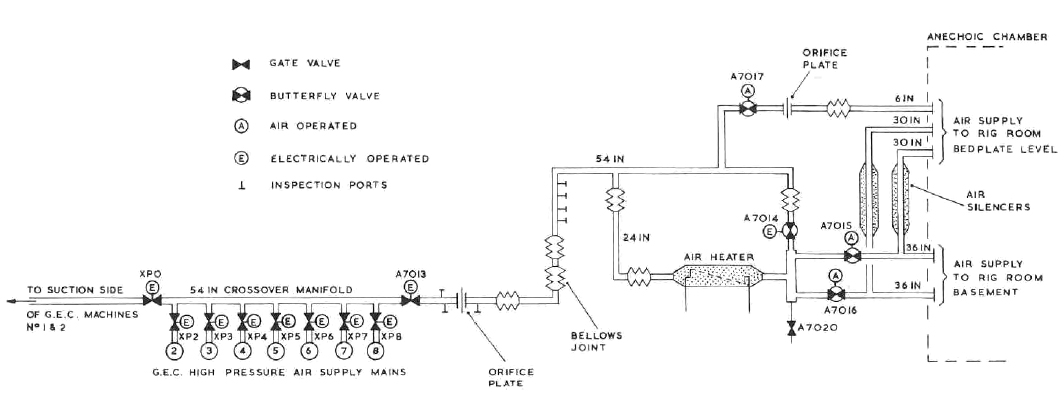
The test rig air supply is provided from the GEC machines in the
Air House, a new 54 in diameter high pressure busmain was connected to
the existing GEC high pressure cross-over main that feeds N.G.T.E. test cells 3 and 4, and which is also
cross-connected to the suction busmains. Normally, up to 200 lb/s at either 3:1 or 9:1 pressure ratio is available;
either by blowing or sucking. It is possible to use the 6:1 Metropolitan-Vickers supply described in Paragraph 8 - when
desirable, becasue these compressors and the Air Bleed Gas Turbine plants are connected to the GEC cross-over main.
Near the Anechoic Noise Test Facility the busmain divides so that the two branches from the single main, 36 in diameter
etner the rig room basement and two 30 in diameter and one 6 in diameter busmains enter the rig room at high level;
the network enables twin-flow rigs to be run if required. Air silencers in the two 30 in mains reduce the noise from
the plant, values and pipework reaching the Anechoic Facility.
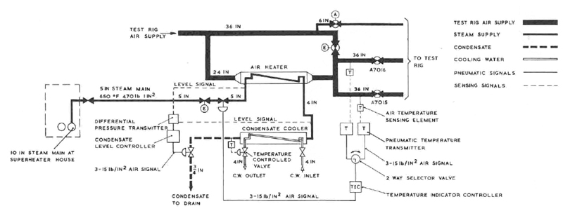
Air preheating to about 200°C may be applied to avoid the possiblity of condensation on
expansion of the air entering the test chamber; for this purpose a steam heated air heater made by Thermo Engineers Ltd.,
is fitted in bypass pipework upstream of the point where the busmain divides, this heater weighing 10,000lb has a heating
surface area of 214 ft2 and a steam side heat transfer rate of 597 BTU/ft2/h. The heater tubes are
made from aluminium finned mild steel and the working fluid makes only one pass. Heating steam is supplied at 400 lb/in2
and 350°C and the air side pressure drop at maximum flow is 1.6 lb/in2. Figure 159 shows the flow route
of the air supply network to the Anechoic Chamber and Figure 160 shows the air heater control system. A general pictorial
view of the air supply services is given in Figure 161, which also show the butane fuel storage tanks in the left centre
foreground.

|
|
Fig. 159. Air Supply to Noise Test Facility Anechoic Chamber.
|
|
|
Fig. 160. Air Heater Control System Noise Test Facility Anechoic Chamber.
|
|
|
Fig. 161. Air Supply Services to Noise Test Facility Anechoic Chamber.
|
On the south side of the Anechoic Chamber structure, a separate windowless brick building,
houses the control and engineering service equipment. This building has three floors and the heavy service plant
is installed on the lower floor with the service supplies fed to the rig room via an underground communication duct;
the main control room is on the middle floor, while the upper floor houses the ancillary electronic equipment and
this may be used for maintenance of all the electronic and instrumentation equipment in the Noise Test Facility. The location
of the control room building may be seen in Figure 142, and a general view of the main instrumentation panels is
shown in Figure 162.
|
|
Fig. 162. The Anechoic Facility Control Room.
|
Data acquisition for the Anechoic Chamber comprises logging systems for aerodynamic pressures, temperatures
and other steady state signals. Unsteady signals from microphones, hot wires, etc., are generally recorded on magnetic tape
for subsequent analysis using the Fourier Analyser described in Paragraph 27, however, limited on-line analysis is also
possible.
347. Data processing for the Noise Test Facility
The study of noise phenomena is to a major extent based on harmonic analysis and therefore equipment
to automatically break down randomly varying signals into their frequency components is an essential tool for research
into noise problems; such equipment uses the two techniques of electronic filtering and direct Fourier analysis.
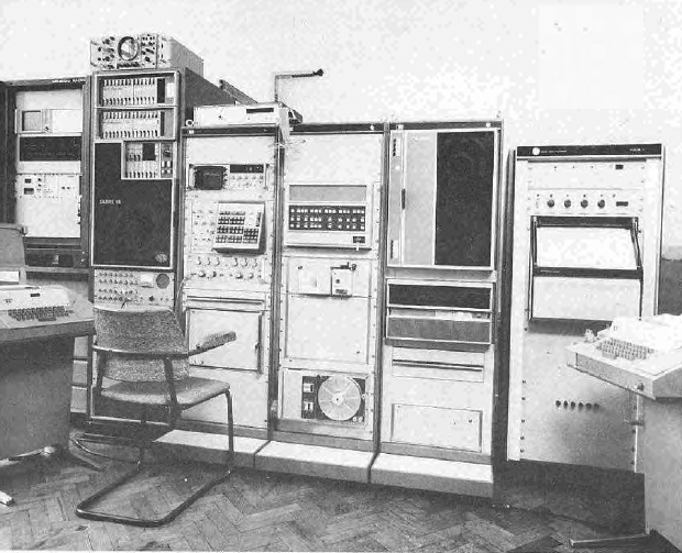
Equipment to digitally process noise data based on the Fast Fourier Transform Algorithm has been installed
at N.G.T.E. and this installation is shown in Figure 163. The equipment is based on a Hewlett Packard 5471A Fourier Analyser
but incorporates a general purpose mini computer type HP 2100A, a special keyboard and display facilities.
|
|
Fig. 163. The N.G.T.E. Noise Test Facility Fourier Analyser.
|
The N.G.T.E. Fourier analysis system aims at providing the noise research worker with a direct method
of data processing without the need for the services of a computer specialist intermediary having an expertise in computers
and software programming; he is able to manipulate and control the equipment directly through twelve simple press buttons
or alternatively, by a conventional teletypewriter. The standard keyboard functions that are availabe are :-
- Forward and inverse Fourier Transform
- Magnitude and phase spectrum
- Power and cross power spectrum
- Transfer function
- Coherence function
- Convolution
- Auto and cross correlation
- Hanning and other weighting functions
- Histogram
- Scaling
- Ensemble averaging
- Real and complex arithmetic
The Fourier Analyser is used primarily for narrow frequency band analysis; for wide band analysis a General
Radio I/3 Octave Analyser is available, the operation of which is based on the electronic filtering technique. The output
of this wide band equipment can be fed into the Fourier Analyser in order to utilise its general computer, storage and
display facilities. Consequently, the wide and narrow band equipments are complementary to one another.
The N.G.T.E. version of the Hewlett Packard Fourier Analyser computer has been extended to incorporate
32K words of random access store, 2.5 million words of disc store, a digital magnetic tape desk and a very fast Varian
Statos 5 analogue plotter/line printer. Together, this equipment forms a flexible system having a powerful capability as
a general purpose computer in addition to that of a Fourier Analyser.
Since the system includes an analogue to digital converter it has the capability of operating both on-line
and in an off-line mode. The policy at N.G.T.E. is to use it in the off-line mode, singals being recorded on analogue magnetic
tape in the N.G.T.E. Noise Test Facility for later processing in the analysis laboratory where a Sabre tape recorder
is available for playing back the signals to the Fourier Analyser; these signals are digitised into blocks of up to 8,000
samples and the frequency resolution of the subsequent analysis is DC - 25 kHz.
This brochrue describes the testing facilities at the National Gas Turbine Establishment in brief outline.
Requests for further detailed information on the scope, and enquires concerning the availablity, of the equipment for
experimental work on behalf of industry should be addressed to :-
- The Director,
- National Gas Turbine Establishment,
- Pyestock,
- Farnborough,
- Hants.
© Procurement Executive, Ministry Of Defence
|