|
 | Electrical, Steam, Water And Fuel Services |
37. Plant Services For Gas Turbine Testing
Certain essential services are required to effectively operate the test plant and
equipment described in the preceding sections; these services are an integral part of the
N.G.T.E. Test facilities without which few of the tests would be possible. This is
particularly true of the major test cells where the sophisticated test equipment requires the full
range of these services.
These services are:-
- high voltage electricity supply and distribution
- high pressure steam supply and distribution
- raw and treated cooling water supply, drainage and effluent treatment
- fuel supplies for engines, and steam raising plant
Although it is not possible to explain in every detail the complexity of these
services, a description is given in para. 38 to 43 of the main arteries and reference is made in
the figures to other drawing refrences from which further detailed information can be obtained. Frequently
the installed services have unique features and the commodity
consumptions are such that the N.G.T.E. has become a very large commercial user
as far as the Public Utility Boards are concerned.
The electrical distribution system is described in para 38. The high consumption
of electricity for gas turbine testing affects the whole life of the Establishment because
it is necessary to carry out many of the tests out of normal working hours. Under the Maximum Demand
charging arrangements the electrical operating costs can be reduced if the Establishment
generates a certain amount of electrical current. If the quantity and the time of generation are
carefully selected it is possible to lop off the consumption peaks so that Maxiumum Demand
charges are considerably reduced. The Establishment therefore, generates sufficient current
to meet its needs whilst restricting the demand on the Generating Board at peak periods to
40MW and off peak periods to 140MW, these quantities to be shared with the Royal Aircraft
Establishment. The details of these operating arrangements are given in para. 39.
As the electrical power generated by the N.G.T.E. is mainly
steam driven, there is a close relationship between steam production and electrical power consumption.
High pressure steam is also required to start and operate the G.E.C. compressor-exhauster machines
and is used extensively for site heating purposes. The Boiler House
is therefore an integral part of the the testing services.
The water distribution systems are described in para 41 and 42. Various grades of water
ranging from raw stock to demineralised water are supplied to the Engine Test Facility and steam raising
plant. The Establishment has found from experience that the use of treated water in the recirculating cooling
systems is economic as maintenance costs are greatly reduced. At one time N.G.T.E. water
supplies were drawn from the Basingstoke Canal, and although the facilities to do this still exist, the
reservoirs today are exclusively filled
with stock drawn from the Mid-Wessex Water Company. The water effluent discharges into the local
streams which are under the jurisdiction of the Thames Conservancy Board and the statutory requirements are
therefore binding on the Establishment and it working procedures must be arranged accordingly. Surface
water drainage presents few problems but effluents from the test rigs can take the form of an oil
emulsion or carry large quantities of soot. Plants have been installed to deal with both of these latter problems
so that the effluent can conform to the standards demanded.
The various types of aviation kerosine, heavy oil and other fuels are supplied under
contract by one of the commercial oil companies and road tankers are used to deliver to site. The
fuel is stored in a tank farm and is pumped to the appropiate local storage areas according to demand.
These services are described in para 43 but the description does not cover in all cases the individual
high pressure pumping arrangements which exist at most of the test cells; this equipment is considered part
of the experimental engineering which is modified to suit particular tests.
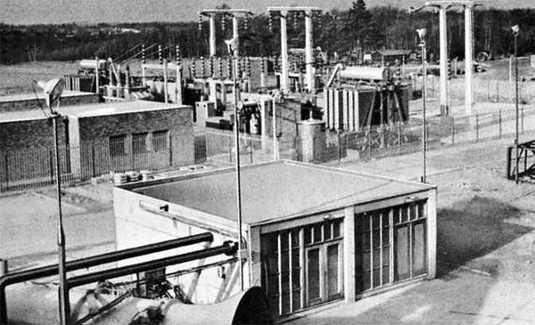
38. N.G.T.E. Electricity Supplies
There are two incoming power supplied and a local power station. The 132kV supply rated at
120MW, is from the C.E.G.B. sub-station at Fleet
which forms part of the national 400kV grid system. This supply feeds four transformers three of which, rated
at 60MVA 132-33kV, feed three sections of the Air House 33kV
bus-bars while the fourth, rated at 30MVA 132-11kV, feeds No. 10
exhauster machine described in para 6. A second supply, which is at 33kV, feed directly into the
fourth section of the Air House 33kV bus-bars and
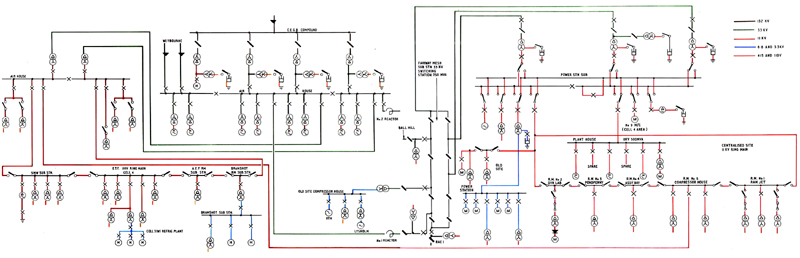
is rated at 40MW. This supply is obtained from the S.E.B. sub-station at Weybourne Lane, Aldershot. Figure 117
shows the C.E.G.B. sub-station at N.G.T.E. while Figure
118 shows the electrical distribution network.
|
|
Fig. 117 The C.E.G.B. electrical sub-station at N.G.T.E.
|
|
|
Fig. 18 Circuit diagram of electrical power supplies at N.G.T.E.
|
Local power generation amounts to 20MW, 18.75MW of this being generated at 11kV, and
the remaining 1.25MW at 415 volts.
- 33kV Distribution: Two sections of the Air House
33kV bus-bars supply power to the Fairway Mesh sub-station via two 30MVA reactors. From this point
power is fed at 33kV to the Old Site also the R.A.E.
Two sections of the Air House 33kV bus-bars supply power to
two 10MVA, 33-11kV transformers local to the Air House. The main
compressor motors in the Air House are
also connected to the 33kV bus-bars.
- 11 kV Distribution: There are two main 11kV distribution systems.
(i) Two 33-11kV transformers, one rated at 15MVA and one at 5MVA, are connected to the Fairway Mesh
33kV bus-bars and supply the Power Station 11kV bus-bars. From these bus-bars
supplies are distributed to the Old Site, the Power Station auxiliaries 11-3.3kV
transformer, the centralised site ring main (Note: this is an alternative feed, see the following
for the usual supply), Plant House machines and
No. 9 compressor motor.
(ii) The two 10MVA 33-11kV transformers, fed from the Air House
33kV bus-bars, feed the Air House 11kV bus-bars. From
these bus-bars 11kV supplies are distributed to the Air House
auxiliaries (four 1MVA 11kV-415V) transformers, the centralised site ring main, the E.T.F. ring main and
Air House cooling towers transformer.
There are numerous 11kV-415V transformers around the site, in the 500 to 1,500kVA range, to provide normal
services to workshops, laboratories, offices, etc. In certain areas other voltages, 3.3kV and 6.6kV are
used and these are porvided via transformers from the 33kV and 11kV distribution systems.
- Air House: Each of the four sections of the Air House
33kV bus-bars supplies two of the main compressor-exhauster motors via a directly coupled 27.5MVA 33-11kV
transformer. Switching is carried out on the 33kV side in order to keep rupturing levels to reasonable
values. In the Air House there is a 0.5MW back pressure turboalternator
able to assist the local generating plant installed in the Power Station
(see paragraph (d)); details are given in Table XIV and para. 40.
- Power Station: Four alternators are installed in the Power Station;
the prime mover and powers are given in Table XIV together with the Air House
back pressure set. With these five plants N.G.T.E. is able to generate a certain amount of electrical power
independent of the elctrical grid supply.
Table XIV
N.G.T.E. Generating Capacity
| Steam Turbine |
12.75MW |
11kV |
3 |
| Gas Turbine |
6.0MW |
11kV |
3 |
| Steam Turbine (Pass Out) |
0.75kW |
415V |
3 |
| Steam Turbine (Back pressure) |
0.50kW |
415V |
3 |
| Diesel |
60kW |
415V |
3 |
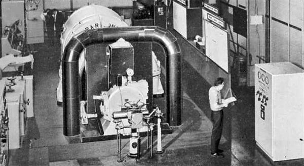
The 12.5MW steam turbine and the 6MV gas turbine were installed as peak lopping sets, the object
being to reduce the Maximum Demand charges in the electricity tariff with a minimum generation of electrical
energy; the 12.75MW turbine is shown in Figure 119. Since the plants were installed however, the tariff structure
has been changed, the M.D. charges have been reduced and the unit charges increased (at certain times in the
year to more than three times an agreed basic charge; these tariffs are listed in para. 39), so the
pattern of operation has now changed and these two alternators now operate as baseload sets during January and
December. During the rest of the year the sets are still used as 'peak load loppers.' The method of operation results
in even larger saving on running the 12.75MW steam turbine, though the saving on the 6MW gas turbine is reduced.
Present figures of saving are �120,000 and �30,000 per annum for the 12.75MW and 6MW set respectively.
The 12.75MW set was installed in October 1962 and paid for itself within three years and thus
the savings are bonuses. The 6MW set was commissioned in June 1967 and will pay for itself in four years i.e. by 1971.
The 0.75MW steam turbine is normally a pass out set, but it is also fitted with a fully condensing system.
During most of the year it operates with minium steam through the condenser, the load being automatically controlled
by the demands of the site heating load which uses the pass out steam. It is however, available for peak load duties up
to 0.75MW at any time using the condenser, and during January and December it acts as a base load set running at its full
output.
The 0.5MW back pressure turbo-alternator in the Air House
provides a useful electrical power bonus from the high pressure steam eventually used for site heating in the
Air House calorifier equipment; the steam passing direct to the hot water
heat exhangers after use in the back pressure set.
The 60kW diesel set is used as an emergency set if normal supplies to
certain important long term tests are interrupted for more than a pre-determined time. It also has the very
important function of supplying certain power station auxiliaries to enable to 0.75MW set to be started.
Once the diesel set is running and generating, the 6MW and 12.75MW sets can be started, thus giving
N.G.T.E. the capability of being able to start-up and generate up to 20MW in the event of a loss of all
external supplies. 20MW is sufficient power to provide the R.A.E. and N.G.T.E. base loads, and even
allows for a small amount of rig testing.
The 12.75MW alternator is also used as a variable frequency source to start the
36,000 h.p. synchronous motor driving No. 9 compressor. The
two machines are electrically coupled together and then synchronised at low speed. The two machines
are run up to grid frequency by increasing the turbine speed and synchronised with the grid;
the starting operations on both machines from barring speed are fully automatic. Once the two machines
are synchronised with the grid, the alternator can be shutdown and/or other equipment can be operated from
the section of the bus-bar used to couple the two machines togehter.
|
|
Fig. 119. The 12.75MW steam driven Bellis and Morcom generator set
|
39 Cost and Limitations to Plant Utilisation due to Electrical Power Supplies
It is very important to note that various electrical restrictions limit the
manner in which the whole of the N.G.T.E. plant can be utilised.
The electricity tariff which has been negotiated between N.G.T.E.
and the Southern Electricity Board (S.E.B.) is similar to that operated by other large power users.
It consists basically of maximum
demand charges to cover the cost of capital equipment and unit charges to cover operating costs.
As with most other commodities, the laws of supply and demand apply, and so these two basic charges
vary, being cheaper at night than during the normal working hours in winter, and continuously cheaper
rated during the summer period. The affect of the capital equipment charge is to introduce periods of
operation when the N.G.T.E. electrical supplies obtained from the grid must not exceed 40MW.
Table No. XV shows the periods when N.G.T.E. supplies are restricted :-
TABLE XV
Electricity Supply Restricted Periods
| November |
1630 to 1830 hours |
| December |
0700 to 1300 and 1630 to 1830 hours |
| January |
0700 to 1300 and 1630 to 1830 hours |
| February |
0700 to 1300 and 1630 to 1830 hours |
| March |
0700 to 1300 hours |
During the periods listed the incoming supply is limited to 40MW and in order to keep
abreast of our test programme the Engine Test Cells which are the large power consumers run only during
the afternoon (13.00 to 16.25) and the evening (18.30 to 22.15)
In addition to this, during the months of January and December, the Central Electricity Generating
Board (CEGB) can issue a 'Potential Peak Warning' indicating that the anticipated demand on the National Grid System
is 90 per cent of its capability. During the 'Potential Peak' periods the Maximum Demand charges are furtehr heavily
increased and therefore during these periods the intake from the supply authority is reduced to zero and N.G.T.E.
generates its own supplies to meet the needs of the Establishment.
In 1969, the four actual Electricity Board tariff rates for electricity actually consumed by
N.G.T.E. are :-
- (a) Cheap night rate which applies between the hours of 23.00 and 07.00 hours throughout the year - 85 per cent of basic.
- (b) Rate 1 which applies during November, February and March between 07.00 and 23.00 hours Monday to Friday inclusive - 1.45 x basic.
- (c) Rate 2 which applies during December and January between 07.00 and 23.00 hours Monday to Friday inclusive - 3.14 x basic.
- (d) Basic rate which applies outside the above hours is 0.67d/unit, plus variable coal charge, which in 1969 will give a total basic rate of 0.76d/unit.
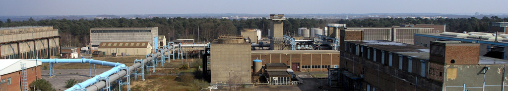
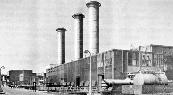
40 N.G.T.E. Steam Supplies (The Battle House)
There are various demands for high pressure super-heated steam on the New Site and in consequence the
N.G.T.E. facilities include a boiler house which houses three marine type water tube boilers each capable
of exporting 150,000lb of steam/h at 400 lb/in2 and 650°F (343°C). The boilers are designed to
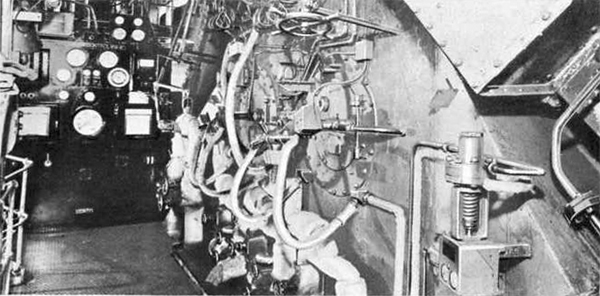
operate with automatic combustion control although steam circuits are set up manually. Pictorial views of the
boiler house are shown in Figures 120 and 121.
|
|
Fig. 120 The N.G.T.E. Boiler House
|
|
|
Fig. 121 One of the N.G.T.E. boiler fronts
|
Steam is required for the following main purposes:-
- Brush Steam Turbine, used for compressor testing. Maximum demand 185,000 lb/h.
- The Air House G.E.C. 8,000 h.p. steam turbines.
Maximum demand 64,000 lb/h of steam each set, eight machines installed.
- THe Power Station Bellis and Morcom steam turbine
generator. Maximum demand 150,000 lb/h.
- Daniel Adamson 750 kilowatt pass-out steam turbine. Maximum demand 25,000 lb/h.
- N.G.T.E. site heating calorifier system. Maximum demand 20,000 lb/h, requirements vary according to
ambient temperature.
- Bellis and Morcom 500 kilowatt back pressure steam turbine. Maximum demand 28,000 lb/h.
- Air House site heat calorifier system. Maximum demand 5,000
lb/h, requirements vary according to ambient temperature.
- Heating medium for the re-activiation of the Ceca air drying
plant. Maximum demand 20,000 lb/h.
Items (4) and (5) are inter-related in that the pass-out steam is used in the site heating
calorifier system. Under this condition approximately 25,000 lb/h of steam will satisfy both services. If the
pass-out turbine is not in operation the calorifiers can be fed direct with live steam and the consumption
falls to a maximum throughput of 20,000 lb/h. In the same way items (6) and (7) are also inter-related
the Bellis and Morcom back pressure turbine will normally provide steam for the
Air House calorifiers, live steam being used when the turbine is out
of action. The present load is restricted to 15,000 lb/h which generates 300 kilowatt of electrical power.
The various demands for setam do not necessarily coincide and the actual total demand
is programmed according to the Establishment's testing programme. When possible, the net export is limited
to 300,000 lb/h so that the steam output is restricted to the flow from two boilers so that one
is available for maintenance overhaul. However, the demand for steam rises year by year and there is now
a trend towards three boiler availability. It is becoming more essential to operate steam driven plant
together and particularly in the winter months, the higher electrical charges make it an
economic proposition for N.G.T.E. to generate as much power as possible to reduce the incoming electrical load;
the net effect is that steam demand is increased.
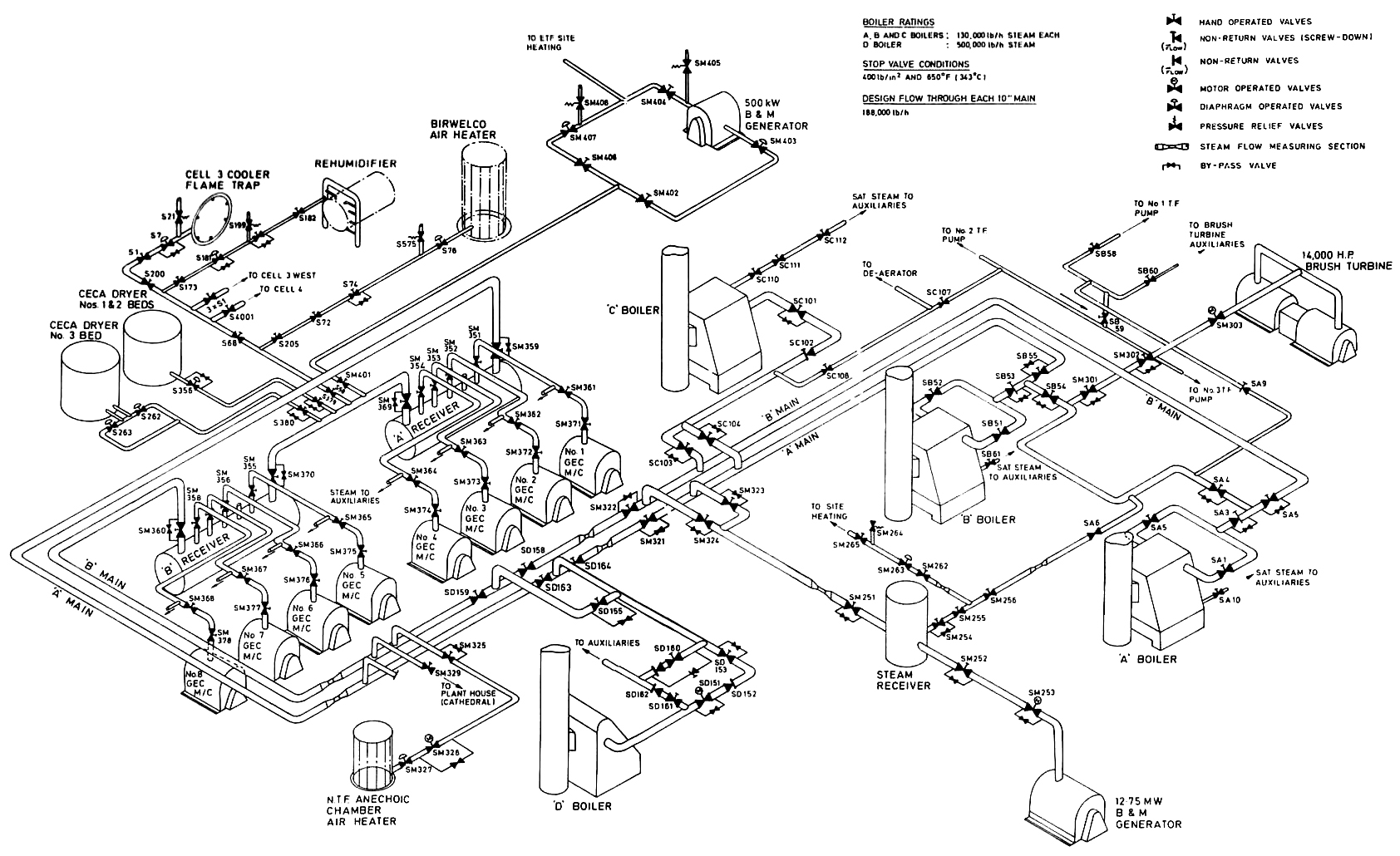
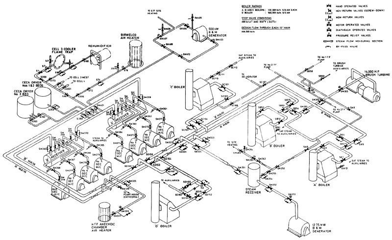
Figure 122 shows a diagrammatic arrangement of the superheated steam distribution network
and the associated control valves. Because the steam used in the Air House G.E.C.
turbines must travel 1,000 yards between the Boiler House and
Air House buildings, a separately fired reheat superheater was originally installed
near to the Air House and 60,000 lb of steam was reheated up to
650°F (343°C); the plant is still available but flows in excess of 50,000 lb/h, an everyday requirement in 1969,
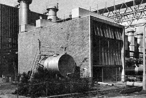
the reheat facility is not really required and it is therefore now considered to be obsolescent. Figure 123 shows
the superheater plant.
|
|
Fig. 122 Arrangement of N.G.T.E. high pressure steam distribution system
|
|
|
Fig. 123 The reheat superheater building
|
Occasionally steam is required for a number of secondary services, these include :-
- Atomising steam for Cell 3 air heater plant.
- Steam for de-icing Cell 3 and
Cell 4 exhaust flame-trap coolers.
- Trace heating steam for heavy residual fuel.
- Low pressure steam for a variety of experimental purposes such as the vaporising of distillate fuels
in experimental test rig fuel systems and other research test rig uses.
Each of these services are provided as and when requrested through the plant centralised
booking arrangements.
Most of the installations have a fluctuating steam demand because of their wide range of
operating conditions and the frequency with which machinery must be modulated to suit engine test programmes
and it was for this particular reason that marine boilers were originally installed at
N.G.T.E. Two of the boilers are ex-Admiralty three drum units built for Battle Class
Destroyers, whilst the third is a five-drum unit built by Messrs Yarrow and Company Limited of Glasgow.
There are no demands for high pressure superheated steam on the N.G.T.E. Old Site and
all heating requiremetns are met from a number of relatively small oil fired boilers located
to supply individual buildings.
Condensate water from the high pressure steam supplies is fed back to
the Boiler House from the
Air House and the Ceca air
drying plants through an 8 inch main. This water is continuously monitored to ensure that it is satisfactory
for re-use. Boiler feed water arrangements are described in paragraph 41.
41 N.G.T.E. Water Supplies
The heavy plant machinery and experimental equipment required for altitude gas turbine testing
needs a plentiful supply of cooling water and for this purpose a complicated network of reservoirs, cooling towers
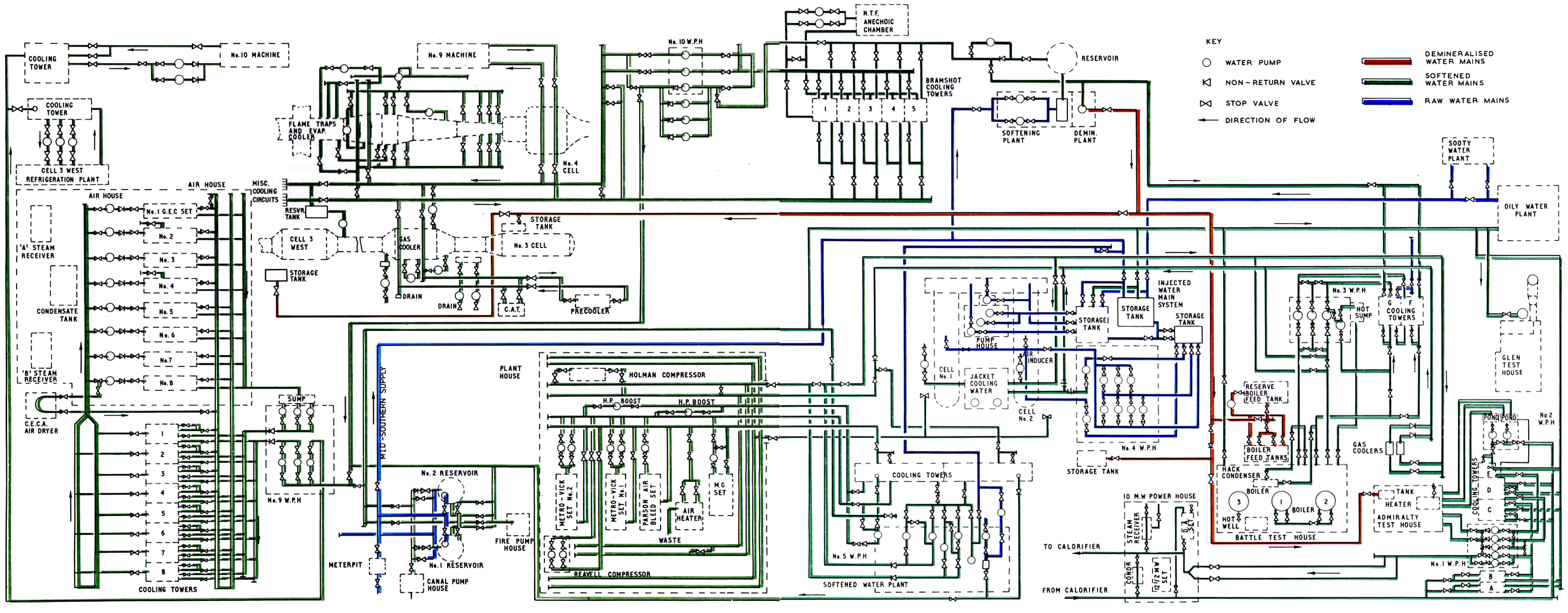
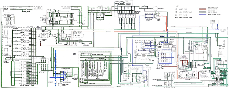
pumphouses and pipe circuits have been installed at N.G.T.E. to meet the need. Figure 124 shows
the circuit diagram for the water system as installed in 1969.
|
|
Fig. 5.8 Layout of N.G.T.E. New Site water supply circuits
|
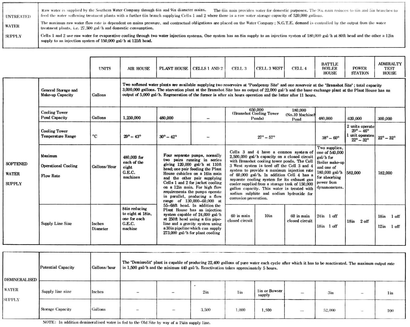
The Establishment uses water of three different qualities on the New Site and
there are three different circuits for distribution; the Old Site system is separate. A summary of the
capacity of the three systems is given in Table XVI. The three New Site systems are :-
- Raw water: Raw water is supplied to the Establishment by the Mid Wessex Water Company via two mains;
one for supplying domestic water in the Establishment's many buildings is 6in diameter, the other, 9in
diameter, is ued to supply the site softened water treatment plants.
Originally raw water was chosen for engine testing and general plant use,
but experience has shown that maintenance troubles and costs are reduced if treated water is used and
the systems were modified so that softened water is generally available. However, it is possible to
supply two of the N.G.T.E. reservoirs with raw water if ever there was a shortage of
softened water because of a breakdown in the treatment plants.
Because engine exhaust gas cooling in Cells 1 and 2 is wholly
by direct injection, as opposed to predominantly indirect cooling systems in most other cells,
Cells 1 and 2 are supplied direct with raw water from the 9in
main and there are available 520,000 gallon capactiy storage tanks adjacent to the test cells.
- Softened water: Although the test plant requires a high flow rate of cooling water, nearly all
tests are of limited duration and consequently the total capacity can be supplied from a storage system
which is replenished during the non-testing period. N.G.T.E. has three main reservoirs,
each having a capactiy of one million gallons, giving a total of three million gallons. Two of the reservoirs
are at the 'Pondpenny' site whilst the third is at the 'Bramshot' site. These reservoirs are continuously
filled with softened water from the treatment plants and there is a 12in bore ring main system through which the
water is distributed to the individual test plants. Most of the larger facilities have their own cooling
tower, each of which has a cooling pond which holds additional supplies of softened water. The main
cooling tower installations are given in Table XVII.
Table XVII
N.G.T.E. Cooling Tower Capacities
| Air House |
1,250,000 gallons |
| Bramshot (Cells 3, Cell 3 West and Cell 4) |
650,000 gallons |
| Plant House |
480,000 gallons |
| No. 10 Machine |
180,000 gallons |
| Battle House |
480,000 gallons |
| Admiralty Test House |
300,000 gallons |
| Power Station |
620,000 gallons |
| Total |
3,960,000 gallons |
The total storage capacity of softened water in the cooling ponds and reservoirs is therefore approximately
seven million gallons.
The calcium carbonate hardness value of the water in the Farnborough locality lies between 175
and 225 ppm and there are two installations used to treat the raw water stock. The larger plant,
located at the Bramshot site, uses the Starvation or HI process which reduced both the hardness and
the alkalinity. This is achieved by passing the water over ion exchange resins whihc break down the
temporary hardness and alkaline salts; this bed is regenerated with dilute sulphuric acid. The capacity
of this plant is 22,000 gal/h and it is capable of working continuously except for the reactivation
period; the plant is automatically controlled. The second water treatment plant is sited near the
Plant House, the equipment uses the base exchange process
which reduces hardness but leaves alkalinity unaffected; this plant has a capacity of 5000 gal/h
and uses brine for regeneration. Both softening plants can work together to fill the reservoirs
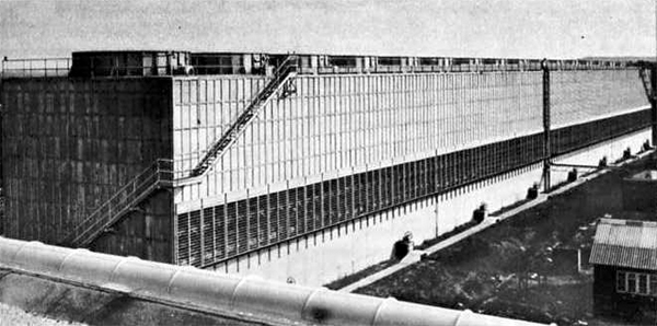
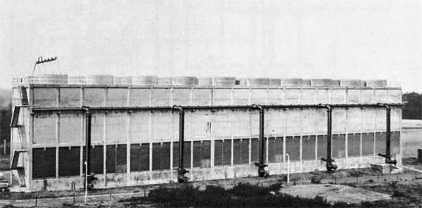
so that the toal water treament capactiy is 27,000 gal/h. Figures 125 and 126 show views of the
Air House and Bramshot cooling towers, whilst the distribution
network for the softened water is shown in Figure 124. The detailed circuits in the individual test
cells and laboratories are not shown but reference is made to N.G.T.E. drawings
and handbooks which give detailed information for the areas concerned.
|
|
Fig. 125 Air House G.E.C. Cooling Towers
|
|
|
Fig. 126 Cooling Towers for engine exhaust in Test Cells 3 and 4
|
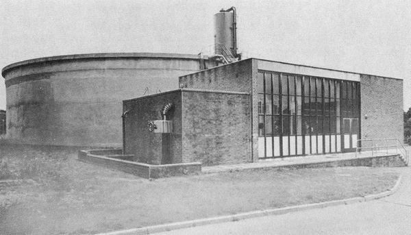
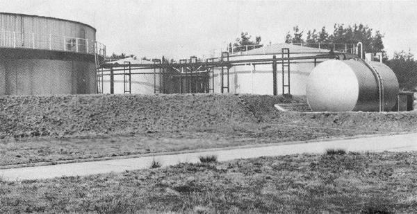
- Demineralised water: For special purposes such as boiler feed water requirements and the
direct injection of water into experimental engine compressors, very pure water is
required and N.G.T.E. has an ion exchange plant to demineralise the
water used in these services. The ion exchange plant is supplied with water already
softened in the Starvation plant, the process removes all minerals and silica in addition
to the reduction of hardness and alkalinity already achieved in the Starvation plant.
Consequently demineralised water has a very high purity, the measured electrical conductivity
is as low as 0.3 reciprocal megohms. Chemcial treatment is used to restore phosphate balance
as well as to scavenge the oxygen and carbon dioxide content.
The installation is sized to match the distilled water demands of the boiler plant and the
capacity is 1500 gal/h, although there is a maximum production limit of 22,400 gallons of
pure water in a twenty-four hour period due to the need to reactivate the ion exchange
resins. The output can be stored for very short periods in a special storage tank at the
Boiler House whilst the plant is reactivated. However,
it should be realised that there is 'conductivity gain' whenever demineralised water is stored.
There is a separate circuit for the distribution of demineralised water, the main 25 gal/min
pump discharge into a 3 inch bore main to supply the Boiler House,
and there is a 2 inch spur for Cells 1 and 2, and 1 inch
supplies to Cell 3,
Cell 3 West and the
Admiralty Test House; the demineralised water circuit is
shown in Figure 124 and Figure 127 shows the plant pictorially.
|
|
Fig. 127 The demineralized water and starvation treatment plant
|
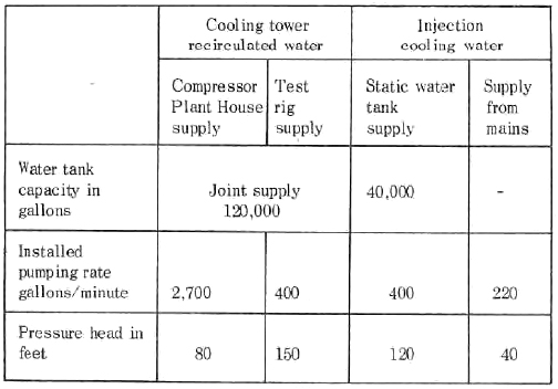
- Old Site water supply: Cooling water is supplied from two sources (i) recirculated water (closed circuit)
through a cooling tower, (ii) mains water which is drained to waste after use. The former is pumped around
a closed circuit and may be used for water jackets, compressor cooling, etc. The latter is available for
direct injection into hot exhaust gas streams.
Table XVI
WATER SUPPLIES FOR N.G.T.E. NEW SITE
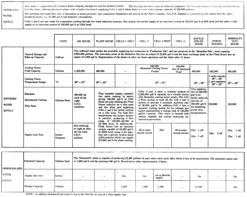
Table XVIII shows the storage capacity, flow and pressure for the Old Site Systems.
Table XVIII
Water storage capacity N.G.T.E. Old Site
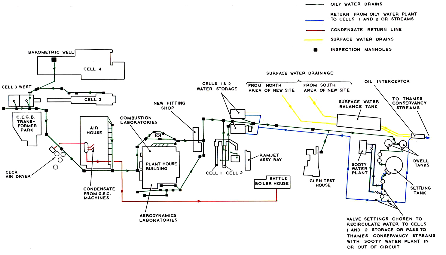
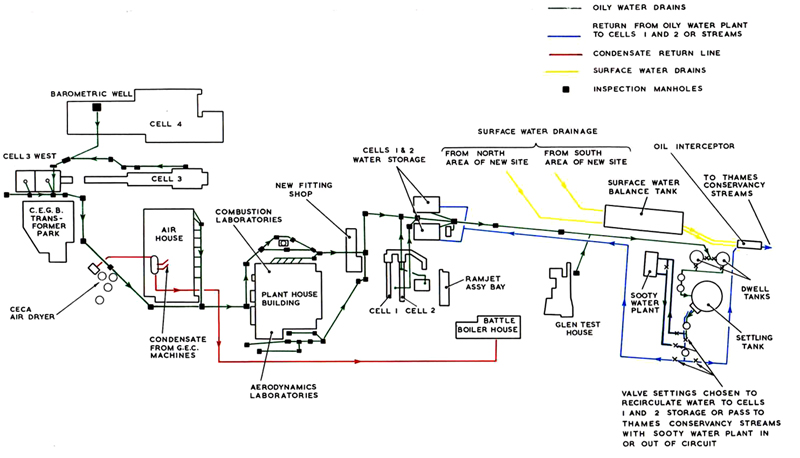
42. Water drainage and effluent treatment
The effluent from the N.G.T.E. site can be separated into two
categories :-
- Clean surface drainage water
- Oil and soot contaminated effluent.
The surface drainage system which drains water from buildings, rainwater pipes,
road gullies, etc., joins two 18in manifolds, one of which collectrs from the area north of the
Air House, including Cell 3
and
Cell 4 area, whilst the other collects from the southern half of
the N.G.T.E. New Site. These drains feed into an open brick storm tank of 750,000 gallons
capacity, which absorbs flood water which would overload the clearwell weirs, and where the water is either
trapped and skimmed so that foreign matter such as oil and grease is removed, or, if free of contamination
allowed to pass through clearwell weirs to the streams which are under the jurisdiction of the
Thames Conservancy Board. This water is closely scrutinised to conform to the Board's standards, which are
that the pH value shall be between 6 and 9, the total solids in suspension not to exceed 30 ppm and the
biochemical oxygen demand not to exceed 20 ppm. Also no toxic substances, oil or greases,
are permissible. Special precautions are taken to treat the water in the storm tank should the
surface water for any reason become contaminated.
The oily water from the test cells and other plant is drained into two
300,000 gallon dwell tanks by way of an 18in bore manifold. The water is allowed to stand in these
two dwell tanks so that the emulsion can be stabilised. The effluent is then pumped automatically
by float controlled pumps into a settling tank of one million gallons capacity. The water effluent
is allowed to remain in this tank for sufficient time for the oil to surface, when it is skimmed
off into troughs and transferred to a 20,000 gallon kerosine dump tank for disposal. The clean
water from the settling tank is pumped automatically at a maximum rate of 30,000 gal/h via the surface water
clearwell weirs, where its quality can be monitored, to the Thames Conservancy streams. Figures 128
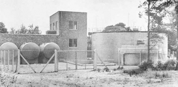
and 129 show views of the oil sooty water dwell tanks and clearwell weirs and Figure 130 shows the
site drainage circuit.
|
|
Fig. 128. General view of oily sooty water receiving tanks
|
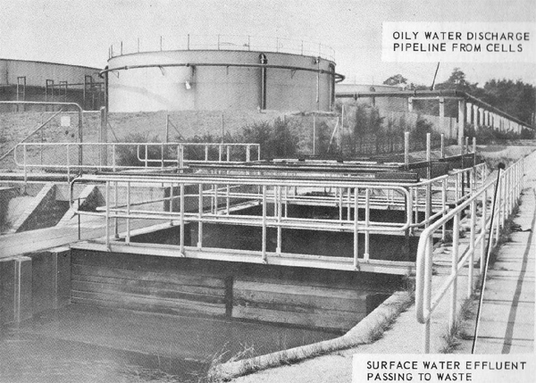
|
|
Fig. 129. N.G.T.E. water effluent disposal plant
|
|
|
Fig. 130. Circuits for N.G.T.E. test cell drainage system
|
When the effluent is sooty as well as oily, the output from the settling
tank which has had the oil removde is re-cycled through a sooty water flocculation plant for processing
instead of passing to the Conservancy Board streams. In this plant the effluent passes into a clarifier where
flocculating additives, Superfloc 16 and Aluminium Sulphate, are introduced. These materials cause the
sooty particles to become negatively charged thus creating greater mutual affinity with each other and a
heavy flock forms so that the particles sink to the base of the clarifier where the sludge is removed.
The clear water from the clarifier is returned to the
Cells 1 and 2 storage tanks for reuse or, when these
reservoirs are full, the excess drains away to the Thames Conservancy streams.
The maximum operational capacity of the sooty water treatment plant is 30,000 gal/h
and its operation is fully automatic. The sludge water is filtered down to 5 microns before it
passes to drain leaving a very small volume of dry carbon waste. The sooty water treatment plant is
shown pictorially in Figure 131.
|
|
Fig. 131. The sooty water treatment plant
|
43. N.G.T.E. fuel supplies
N.G.T.E. has its own fuel storage tank farm and pumping arrangements. There are two
separate systems, one (a) on the New Site and the other (b) on the Old Site. In each installation a
number of different fuels can be stored and pumped to local tanks or fuel systems at the individual
test cell or experimental rig, according to need. The New Site system also provides the heavy fuel
for the Boiler House which is the best 'customer'
for fuel because the boilers are in continuous twenty-four hour service.
Fuel is supplied under contract by one of the major oil companies and
their tankers deliver daily to the tank farms. Normal Bowser connections are used to discharge the fuel load
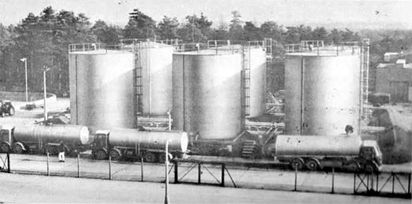
into the storage tanks. Although tests are often run on special fuels, by far the heaviest demand is made for
heavy fuel oil and aviation kerosine. Figure 132 shows the New Site fuel tank farm pictorially.
|
|
Fig. 132. N.G.T.E. New Site fuel tank farm viewed looking east
|
|
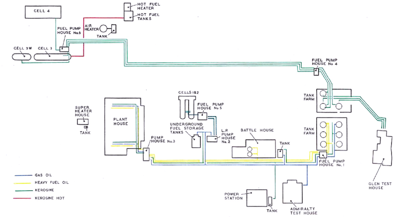
(a)
|
New Site fuel system: The New Site tank farm has two bunds, one having six 80,000 gallon tanks and the
other three 80,000 gallon tanks, making a total of nine. Although most of these tanks can hold different fuels so
that the fuel holding can be varied according to need, a pattern has been established so that certain fuels are
now usually held in particular tanks, in fact the tanks in the smaller bund (No. 107 to 109) only store
kerosine although a changeover to other fuels such as gas oil could be arranged if neccessary. Fuel from
the small farm is pumped through three 6in lines to Cell 3,
Cell 3 West and
Cell 4 and also to the Glen Test House as shown in Figure 133
which outlines all the New Site fuel system circuits. The six tanks in the larger bund (No. 101 to 106) supply
four different fuel pipelines, two of 6in and two of 3in diameter; the 6in lines normally carry heavy grade fuel oil
of 3000 second Redwood viscosity and these pipes, which connect with the
Battle Boiler House and the
Plant House laboratories where combustion tests with heavy fuel are
conducted, are externally lagged and steam traced. The two 3in lines carry distillate fuels, either kerosine, gas oil or
wide cut gasoline. These lines connect with the
Plant House laboratories,
Power Station and
Admirality Test House and there are cross-connections with the underground
storage tanks in Cells 1 and 2. The tanks in
Cells 1 and 2 can be filled direct from road tankers because the
system has its own built-in Bowser conenctions. There are six pump houses in all on the New Site, and in each
there are pump installations to circulate fuel to the test rigs.
Figure 133 shows the permanent pipework installations but no attempt is amde
to show the individual experimental rig systems because these are considered to be a part
of the experimental arrangements and in any case it is usual practice for the local
high pressure pump, relief and control valves, to be engineered as a part of the
experimental equipment and to modify the components to suit each engine or rig installation.
Detailed information on the experimental part of the systems is available in a number of
N.G.T.E. publications and these are cross-referenced in Figure 133, these handbooks also
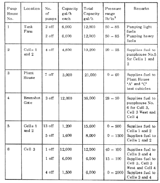
described the Pump House equipment in detail although some information on the capacity is given in Table XIX.
The hot fuel system which at present only supplies hot fuel to Cell 3
is described in paragraph 18.
|
|
(b)
|
Old Site fuel system: The fuel installation on the Old Site consists of a bund holding three tanks, each of 2,300 gallons
capacity, so that three separate fuels can be stored; normally, two of the tanks hold kerosine. Each tank is fitted
with its own reversible pumping system so that the fuel can be supplied to the test laboratories described in
paragraph 29 as required, the pumps have a variable discharge of 0 to 1800 gal/h at a constant head of 30 lb/in2
and the fuel delivery pipes are 2in diameter. As in the case of the New Site fuel system, the high pressure pump and control
valves for the rigs are engineered as part of the experimental equipment. Each of the three fuel circuits has a jettisoning
arrangement so that fuel can be quickly returned to the storage tanks in the event of fire or similar hazard at the
rig; operation of the actuator button in the test laboratory reverses the pump direction instantly so that the
fuel flow direction is reversed.
The three oil fired boilers used for Oil Site heating have their own local fuel system
and storage tanks which are replenished by road tankers as required.
|
|
|
Fig. 133. Layout of New Site fuel distribution system
|
Table XIX
New Site Fuel System Pumping Capacity
© Procurement Executive, Ministry Of Defence
|