|
|
|
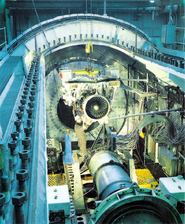
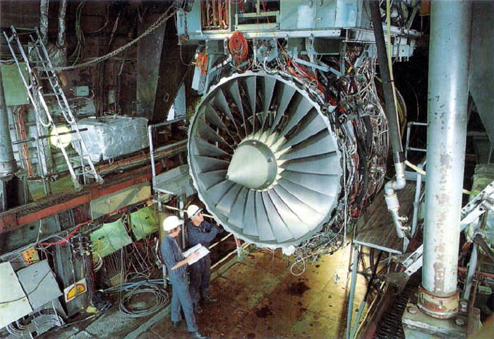
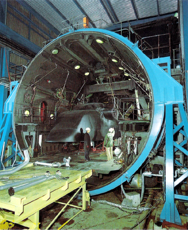
Engine installation in Cell 3.
|
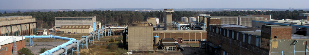
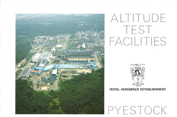
Pyestock is located near Farnborough, Hampshire, South-East England, 35 miles South-West of London. The 250 acre site contains
the most comprehensive range or aero engine altitude test facilities in Europe. It originated in 1946 when the Engine Department
of R.A.E. Farnborough merged with the Whittle Power Jets team to form The National Gas Turbine Establishment. In 1983 Pyestock became
part of the R.A.E., the major air system research establishment of the Ministry of Defence Procurement Executive.
There are five altitude test cells which between then can cover tests ranging from sea-level to 70,000 feet altitude and forward
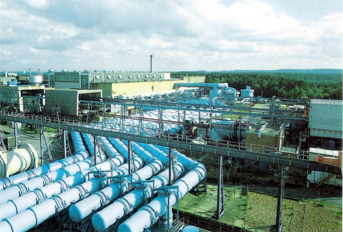
speeds up to Mach 3.5. The cells are provided with air by a centrally situated air processing plant capable of
delivering up to 1200 lb per second of air and absorbing up to 120 MW of electrical power. Large diameter pipes deliver
air from the generating compressors to the test cells and also duct the exhaust gases from the cells back to atmosphere through
exhausting machinery.
Military engines which can be tested range from small missile power plants of 60 lb thurst to military combat aircraft engines
in full reheat, delivering 20,000lb thrust. Civil engines can also be tested up to 65,000lb thrust.
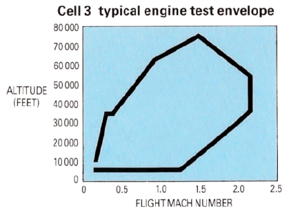
With an engine rigged in the connected test mode, steady state engine performance can be measured anywhere within the typical
test envelope illustrated below. The engine can also be acclerated and decelerated in response to throttle movement to explore its
dynamic behaviour. Test conditions of altitude and Mach number can be changed rapidly during a test (although not in aircraft
mission real time) enabling many flight conditions to be simulated during a half-day testing session.
Cell 3 is mainly used for miltary engine testing. The engine is lowered into
the test cell through an access lid on the top and the lid is then bolted down to form a pressure vessel. The cell is 20ft internal
diameter and the working section is 56ft in length.
Test requirements that can be met include:
- Steady state performance measurement
- Control system evaluation
- Relight at altitude
- Limits of combustion stablity
- Evaluation of behaviour in severe icing conditions
- Tolerance to distorted inlet flows
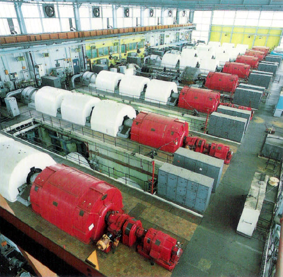
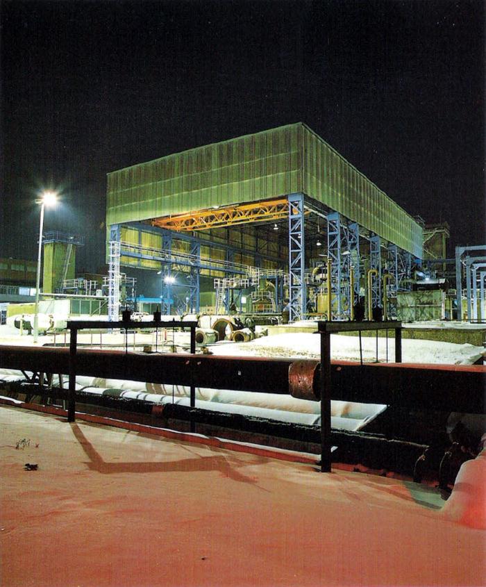
Air House Machinery
The Air House contains eight electrically driven
compressor/exhauster sets which can be used to supply high pressure air to the inlet of military
engines to simulate high forward speed at low altitude. These machines can also extract the engine
exhaust gases and lower the cell pressure so producing the required altitude conditions. There
are two other compressor sets on site that can be used for exhaust duties only. A typical miltary
combat engine test might need two machines compressing at a pressure ratio of 9:1 for air delivery
and three operating as exhausters at a pressure ratio of 3:1. In constrast, a large civil fan
engine drawing its inlet air from atmosphere might need nine of the available 10 machines on site
for the exhaust extraction duty.
|
|
Exhaust/air suction mains
|
|
|
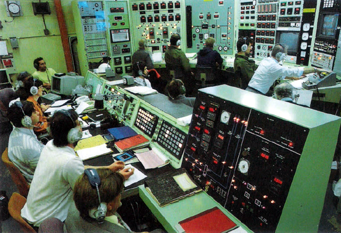
Air House control room
|
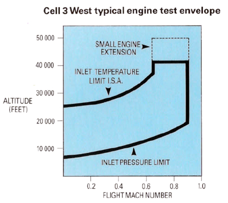
Cell 3 West has an internal diameter of 25ft and the working section is
30ft in length. It is mainly used for civil fan engine testings and unlike Cell 3
has an atmospheric inlet. Air is drawn through an inlet cooler through which refrigerated ammonia is circulated at temperatures
down to -50°C. The air temperature can be reduced to -40°C which is appropiate to a civil aircraft crusing at an
altitude of 40,000ft. Cell 3 West is capable of the same type of tests as
Cell 3.
|
|
Engine installation in Cell 3 West
|
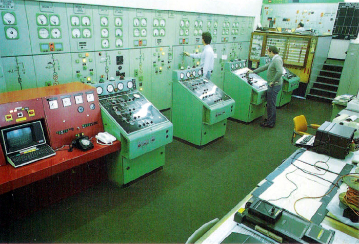
Each test cell has a control room dedicated to it in which the test control team set up test conditions and control the test.
|
|
Cell 3 test control room
|
The test cells are all linked with a central computer controlled data gathering system which enables the tests to be monitored
on-line using graphical displays on video units. Pyestock Engineers can use this system to check that the test plant is set up
correctly and producing the right flight conditions whilst the customers' engineers can evaluate the engine or rig performance
during the course of the tests.
|
|
Test cells 1 and 2
|
Other test cells on the site include:
- Cell 2 - which is similar in many respects to Cell 3 but
does not have a cold air inlet and has a restricted test envelope.
- Cell 1 - is very similar to Cell 2.
- Cell 4 - is a supersonic free jet test facility used for engine intake compatibility testing
but not in current use.
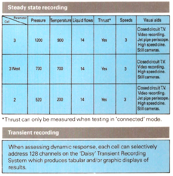
The instrumentation capabilities are very broad and vary from cell to cell. The following tabulation gives a summary of the numbers
of parameters which can be recorded in the three active test cells.
Non aero-engine work can also be undertaken in the Pyestock facilities. With cells rigged in the free-jet test mode, icing
tests on full scale helicopter and engine intakes are examples of such use.
|
|
A full scale model helicopter fuselage positioned in Cell 3 West for
engine intake icing trials
|
|
|
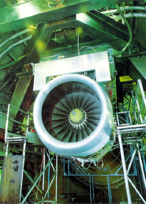
V.2500 engine and intake assembly rigged for free jet icing tests in
Cell 3 West
|
For further information on the capabilities of the altitude test cells at Pyestock enquires should be addressed to Head of
Propulsion Department, RAE Pyestock, Farnborough, Hants. GU14 OLS.
|